
Circuit Diagram
Index 767
ELECTROSTATIC_PROTECTOR
Published:2009/7/17 2:27:00 Author:Jessie

A simple way to protect the gate of a power MOS device is to place back-to-back zener diodes between the device's gate and source (a). The breakdown voltage of the zeners is chosen to be less than the oxide-rupture voltage so that the ESD transient cannot harm the gate. The resistance of the clamp diodes must be kept to a minimum because ESD transients can have high peak currents (in amps), and the voltage appearing at the gate will be the sum of the zener breakdown voltage and the IR voltage drop across the diode resistance. The machine model (MM) is particularly stressful because there is no resistance to limit the current. Along with the diodes, the resistor (RG) is added to improve MM performance. RG prevents the gate of the MOSFET from charging to a dangerous voltage level during the time the ESD transient is dissipated by the diodes. A machine model here is defined as a 200-pF capacitor with no series resistance. (View)
View full Circuit Diagram | Comments | Reading(986)
SIMPLE_LOW_FREQUENCY_RECEIVER
Published:2009/7/17 2:26:00 Author:Jessie

Using an NE602 heterodyne detector and U1 as an RF amplifier, this receiver tunes the middle portion of the low-frequency spectrum from 150 to 250 kHz. U2 is a loudspeaker amplifier. (View)
View full Circuit Diagram | Comments | Reading(2570)
IN_CIRCUIT_TESTER
Published:2009/7/11 5:25:00 Author:May
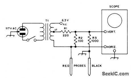
Eliminates need for removing components one by one for testing. Voltages and currents used are low enough for almost any transistorized circuit. Will test for shorts and opens. Shows folward-reverse ratios on junction transistors and diodes. Lissajous figures and other combination displays on CRO facilitate analysis of circuits having reactive components, transistors, and ICs. Will detect high-resistance solder joint and check continuity of switches, fuses, lamps, and printed wiring. Displays form hands of clock or ovals. Vertical line indicates short, horizontal means open, slant indicates resistance, vertical oval is inductance, horizontal oval ii capacitance, diode and highest-merit transistor show 3 o'clock, fair transistorshows 4 o'clock, and poor transistor shows 5 o'clock. For other patterns, compare with those obtained with known good components.-D. L. Ludlow, The Octopus, QST, Jan. 1975, p 40-42. (View)
View full Circuit Diagram | Comments | Reading(3534)
5_DIGIT_PRESET_COUNTER
Published:2009/7/11 5:24:00 Author:May
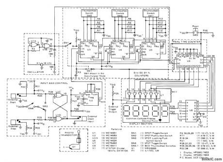
Basis of circuit is Motorola CMOS real-time MC14534 five-decade counter containing five ripple-type decade counters whose outputs are time-multiplexed by intemal scanner. Time-base oscillator pro-vides 10-kHz crystal reference for clocking counters. Total current drain of system is 65 mA from 5-V supply. When used to control quantity of items placed in carton, each item interrupts light beam of photoelectric system to give count. External trigger output is connected to control mechanism that advances conveyor belt when box is full. Quantity of items desired per box is dialed on thumbwheel switches. Dis-play is used to indicate number of boxes filled. Other applications include count and display of number of interruptions of light beam, mea-surement of conveyor speed, and measurement of log lengths in sawmilL-A. Mouton, Five Digit Accumulator/Elapsed Time Indicator, Motorola, Phoenix, AZ, 1975, AN-743 p 3. (View)
View full Circuit Diagram | Comments | Reading(3621)
TRANSISTOR_POWER_GAIN
Published:2009/7/17 2:26:00 Author:Jessie
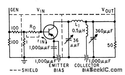
Measures power gain as a function of frequency. When maximum oscillation frequency is approached, unilateral gain drops at rate of 6 db per octave. Input generator has 1 ohm internal resistance. Pi network matches transistor output to load resistor.-J. Lindmayer and R. Zuleeg, Determining Transistor High-Frequency Limits, Electronics, 32;34, p 31-33. (View)
View full Circuit Diagram | Comments | Reading(912)
OVER_UNDERVOLTAGE_PROTECTOR
Published:2009/7/17 2:26:00 Author:Jessie

The ICL7665 over/undervoltage detector manufactured by Maxim (IC1) monitors the line voltage and disconnects the load if the input voltage goes below 95 V or above 130 V. The over/under-voltage detector (IC1) monitors the filtered, unregulated dc voltage developed across C5, which changes with the input line voltage. The input voltage levels to IC1 are set by resistors R2 through R8. As long as the voltage at pin 3 is above 1.3 V and the voltage at pin 6 is lower than 1.3 V, both outputs (pins 1 and 7) are low and RY1 is turned on and its contacts are closed. The average line voltage varies at different locations. Trimmer potentiometer R4 provides a small adjustment range so that you can set the window's center for your particular line voltage. When IC1 detects an overvoltage at pin 3, it immediately opens the relay by sending a high output to pin 2 of NOR gate IC3-a, which, in turn, turns off Q1. When IC1 detects an overvoltage at pin 6, the output at pin 7 goes high. Monostable multivibrator IC2 provides a 1/2-s delay to keep RY1 turned off long enough for the voltage across C5 to return to normal. When pin 7 of IC1 goes high, it triggers IC2, and the high output at pin 6 of IC2 causes the output of NOR gate IC3-a to go low, which turns Q1 off and deenergizes RY1. Switch S2 lets you quickly check the circuit's operation at any time. Pushing S2 raises the voltage at the junction of R2 and R5 and turns RY1 off. RESET switch S1 restores normal operation. Switch S1 turns the circuit on initially. An LM7805 voltage regulator (IC4) provides a constant 5-V supply for the integrated circuits and the relay control current. (View)
View full Circuit Diagram | Comments | Reading(1247)
TUNABLE_PHASE_SHIFT_NETWORK
Published:2009/7/17 2:25:00 Author:Jessie

Frequently, the need arises to control the phase shift or delay of an audio signal. The all-pass active filter shown performs this function. The transfer function has the form
T(S)=Vout (S)/Vin(S)=1-sRC/Vc/(1+sRC/Vc)
where Vc is the control voltage and Vc > 0. As a result, this filter has unity voltage gain for all frequencies. Vc can be used to vary the phase over the theoretical range from -180°≤φ≤0. In the circuit, the left op amp and analog multiplied combination produce an inverting, first-order, low-pass filter whose pole frequency is set by the control voltage, according to ωp=VC/RC. An MC1495 analog multiplier has an adjustable scale factor, which, in this case, is set to 0.1 for convenience. Choosing a center frequency of fo at the geometric mean of the audio range, or fo= √20×20KΩ=633 Hz, centers the phase shift at -90°. For VC=1Vdc, using the relationship fo-VCωo/2π=VC/2πRC sets the RC time constant to 252μs. Selecting R 10 kΩ makes C 25 nF. (View)
View full Circuit Diagram | Comments | Reading(899)
LOG_ATTENUATOR_FOR_POSITIVE_PULSES
Published:2009/7/17 2:25:00 Author:Jessie

Output is proportional to log of input voltages between 0.1 and 100 V.-C. D. Nail, Logarithmic Attenuator Spans Three Decades, Electronics, 36:46, p 47-48. (View)
View full Circuit Diagram | Comments | Reading(825)
35_TO_10_MHz_SIMPLE_SUPERHETERODYNE_RECEIVER
Published:2009/7/17 2:25:00 Author:Jessie


In this circuit,U1 is a frequency converter that feeds the 455-kHz IF stage U2 and detector U3. U4 is the audio output stage. R9 is a gam control that vanes the gam of U2.Coil dataisgtven h the part list. (View)
View full Circuit Diagram | Comments | Reading(5633)
R_F_TRANSMITTER_POWER_AND_VSWR_MONI_TOR
Published:2009/7/17 2:24:00 Author:Jessie

Standing-wave ratio is indicated by position of shaft of potentiometer R7 in bridge circuit, when switch is in vswr position. Diodes D3 and D4 act with Q1 as alarm circuit that interrupts power amplifier plate voltage when vswr exceeds preset limit. At other switch position, actual r-f output power in watts is indicated on d-c milliammeter.-L. F. Stein, Versatile R.F Monitor Shows Power and VSWR, Electronics, 36:13, p 44-46. (View)
View full Circuit Diagram | Comments | Reading(908)
DELAYED_ACTION_MOBILE_RADIO_PROTECTION_CIRCUIT
Published:2009/7/17 2:23:00 Author:Jessie

This circuit uses an SCR and an RC circuit to delay application of power to a mobile radio or other equipment. This is to provide protection from starting motor- and alternator-induced transients. (View)
View full Circuit Diagram | Comments | Reading(660)
COATING_THICKNESS_GAGE
Published:2009/7/17 2:23:00 Author:Jessie

Oscillator V1 and amplifier V2-V3-V4 apply 10-cps signal to magnetic-reluctance transducer held over coating up to 0.040 inch thick, unbalancing transducer and giving output voltage proportional to thickness of coating. (View)
View full Circuit Diagram | Comments | Reading(727)
1_TRANSISTOR_REGENERATIVE_RECEIVER
Published:2009/7/17 2:22:00 Author:Jessie

Using an MPF102 FET, this one-transistor radio receiver is suitable for experimental use. It can tune 4 to 26 MHz. For speaker operation, a simple IC amplifier can be used. (View)
View full Circuit Diagram | Comments | Reading(4330)
DIAMOND_CIRCUIT_MEASURES_A_F_PHASE_SHIFT
Published:2009/7/17 2:22:00 Author:Jessie

Accuracy is 1%UP to 2,000 cps. Used in computers and for high-speed analog instrumentation. Zero-center d-c ammeter indicates negative value for zero phase shift, zero for 90° phase shift,and some maximum value for 180° phase shift.-H. R. Deveraux, Diamond Circuit Measures Phase Shill,Electronics,37:25,p 74-75. (View)
View full Circuit Diagram | Comments | Reading(1078)
12_V_AT_150_mA
Published:2009/7/17 2:21:00 Author:Jessie

Designed for use with audio preamρs, FM tuners, and stereo decoders for which minimum ripple, minimum noise, good regulation, and good temperature stability are important. Uses 5.6-V reference zener that is fed from output but is inside feedback loop. Un-regulated input can be up to 36 V.-M. L. Old-field, Regulated Power Supplies, Wireless World, Nov. 1972, p 520-521. (View)
View full Circuit Diagram | Comments | Reading(692)
126_V_AT_3_A_1
Published:2009/7/17 2:20:00 Author:Jessie

Will handle typical 15-W 2-m transceiver Short-circuit protection is provided by 82-ohm resistor Adjust value of resistor marked 2.4K to give desired output voltage Transformer secondary is nominally 35 V center-tapρed at 1.5 A Output capacitor can be tantalum-slug electrolytic with any value above 10 μF.-H. H. Cross, The Chintzy 12, 73 Magazine, Feb. 1977, p 40-41. (View)
View full Circuit Diagram | Comments | Reading(701)
MEASURING_TRANSISTOR_OPEN_CIRCUIT_OUTPUT_ADMITTANCE
Published:2009/7/17 2:20:00 Author:Jessie

Test set gives smallsignal value h-ob of open-circuit output admittance of transistor for common-base connection. Input voltage is held constant at 1 V and current is read as voltage drop across 1K resistor. Voltage in mv can then be read directly as admittance of 0.1 to1 micromho on 10-mv scale of meter.-Texas Instruments Inc., Transistor Circuit Design, McGraw-Hill, N.Y., 1963, p 71. (View)
View full Circuit Diagram | Comments | Reading(1070)
DIODE_RELAY_DRIVER_PROTECTION
Published:2009/7/17 2:19:00 Author:Jessie

The diode protects the switching transistor from the voltage spike caused by the relay coil. (View)
View full Circuit Diagram | Comments | Reading(835)
MAGNETIC_TAPE_FLUTTER
Published:2009/7/17 2:19:00 Author:Jessie

Time of travel of recorded pulse between two playback heads on lope recorder under lest is converted to d-c voltage. Boxcar detection circuit, ramp generator, and sampling gate detect flutter components as small as 0.01 % peak-topeak.-A. Schulback, Instantaneous Measurement of Tape Flutter, Electronics, 35:19, p 93-94. (View)
View full Circuit Diagram | Comments | Reading(828)
MEASURING_TRANSISTOR_SHORT_CIRCUIT_INPUT_RESISTANCE
Published:2009/7/17 2:16:00 Author:Jessie

Output meter gives direct reading of h-ib when input current is held at 1 microamp.-Texas Instruments Inc., Transistor Circuit Design, McGraw-Hill, N.Y., 1963, p 70. (View)
View full Circuit Diagram | Comments | Reading(679)
| Pages:767/2234 At 20761762763764765766767768769770771772773774775776777778779780Under 20 |
Circuit Categories
power supply circuit
Amplifier Circuit
Basic Circuit
LED and Light Circuit
Sensor Circuit
Signal Processing
Electrical Equipment Circuit
Control Circuit
Remote Control Circuit
A/D-D/A Converter Circuit
Audio Circuit
Measuring and Test Circuit
Communication Circuit
Computer-Related Circuit
555 Circuit
Automotive Circuit
Repairing Circuit