
Circuit Diagram
Index 769
DIGITAL_SAWTOOTH_GENERATOR
Published:2009/7/17 2:04:00 Author:Jessie
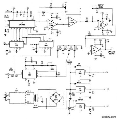
This straightforward circuit uses an NE555 timer as an oscillator, a 7493 counter chain and a DAC0806 D/A converter. The counter output feeds the DAC, producing a linearly increasing voltage, which drives an op amp and a dc-level insertion circuit. The clock frequency must be 256 times the desired sawtooth output frequency.
(View)
View full Circuit Diagram | Comments | Reading(2015)
CAPACITANCE_TRACKING_TEST_SET
Published:2009/7/17 2:03:00 Author:Jessie

Output signal voltage of capacitance bridge, proportional to capacitance unbalance, is applied to vertical input of scope through 1-Mc preamp. Horizontal sweep voltage of scope is also applied as bias to voltage-variable capacitances VVC whose tracking is being measured, so scope display shows diode capacitance-tracking as function of bias voltage.-L. A. Weldon and R. L. Kopski, Boost for Electronic Tuning, Electronics, 37:14,p 61-63. (View)
View full Circuit Diagram | Comments | Reading(1072)
STRETCHER_EXPANDER
Published:2009/7/17 2:03:00 Author:Jessie
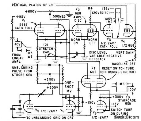
Produces dot pulse and inverted for push that unblanks crt screen and advances staircase.0.5-microsec pulse from linear amplifier is stretched to 2-millisec pulse, amplified and inverted for push-pull crt deflection.-W. E. Bushor, Sample Method Displays millimicrosecond Pulses, 32:31, Electronics, p 69-71. (View)
View full Circuit Diagram | Comments | Reading(578)
STRAY_CAPACITANCE_CANCELLATION_TECHNIQUE
Published:2009/7/17 2:03:00 Author:Jessie
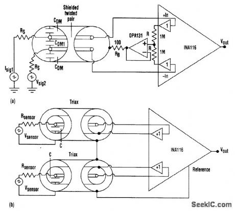
A shielded twisted-pair cable eliminates common-mode capacitance, but the differential capacitance remains (a). A triax cable eliminates both common-mode and differential capacitances (b). (View)
View full Circuit Diagram | Comments | Reading(750)
R_C_DIRECTIONAL_COUPLER
Published:2009/7/17 2:03:00 Author:Jessie
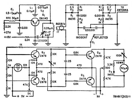
Couples variable-frequency 150-175 Mc oscillator to vhf antenna and furnishes incident and reflected power samples to d-c amplifier for measuring voltage-standing wave ratio.-J. Hanson, Unconventional Technique for Measuring VSWR, Electronics, 32:43, p 120-121. (View)
View full Circuit Diagram | Comments | Reading(674)
TEMPERATURE_COEFFICI_ENT_COMPUTER
Published:2009/7/11 5:16:00 Author:May
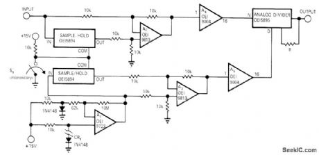
Circuit automatically measures and calculates temperature coefficients of analog circuits or devices. Silicon diode CR1 is used as temperature probe having forward drop of about 2 mV/ ℃. R adjusts output scale factor, FET-input opamp A1 converts forward voltage drop of temperature probe into high-level analog voltage that varies 325 mV/℃ from -10V at +55℃ to 10 V at -5℃. Output of A1 is applied to sample-and-hold circuit, while analog voltage from device under test is applied to second sample-and-hold. Momentary closing of S1 causes volt-age and temperature data to be stored in sample-and-hold circuits at start of test to bias a2 and A3. Outputs of these opamps can be positive or negative, butare made poshive by unity-gain absolute-value opamps A4 and A5. From these outputs, analog divider calculates temperature coefficient.-R. C. Gerdes, Temperature-Coefficient Measuring Circuit, EDN/EEE Magazine, Feb. 1, 1972, p 54. (View)
View full Circuit Diagram | Comments | Reading(785)
_12_V_AT_50_mA
Published:2009/7/17 2:02:00 Author:Jessie
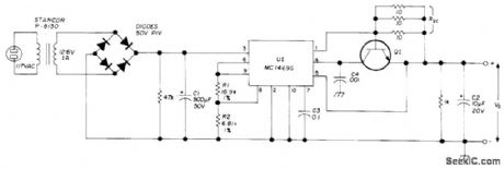
Provides 0.1% regulation as required for PLL RTTY tuning unit and other critical applications. RSC and Q1 provide short-circuit protection for regulator.When output current reaches about 200 mA, Q1 turns on and limits regulator output. U1 can be Motorola MC1469G or HEP C6049G, and at is any general-purpose NPN silicon transistor.-E. Law-rence, Precision Voltage Supply for Phase-Locked Terminal Unit, Ham Radio, July 1974, p 60-61. (View)
View full Circuit Diagram | Comments | Reading(601)
FREQUENCY_MULTIPLIER_MMIC_AMPLIFIER
Published:2009/7/17 2:02:00 Author:Jessie
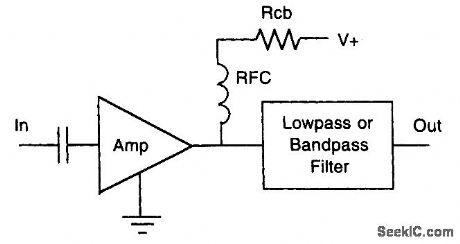
With sufficient drive, an MMIC can be an efficient frequency multiplier. (View)
View full Circuit Diagram | Comments | Reading(613)
28_MHz_TO_220_MHz_FOR_TRANSMIT
Published:2009/7/11 5:16:00 Author:May

Permits use of 2-meter transceiver to transmit in 220-MHz band with minimum of 6-W power output for 1-W drive on 28 MHz Local-oscillator output at 192 MHz can be used for receiving converter as well Use 8-pF butterfly-type air variable(Johnson 160-028-001)for C24, C26, C28, and C32,D1 is GE ZD8. 28-V1-Wzener,-F. J. Merry、A220-MHz Transmit Converter, QST, Jan, 1978, p 16-20. (View)
View full Circuit Diagram | Comments | Reading(1236)
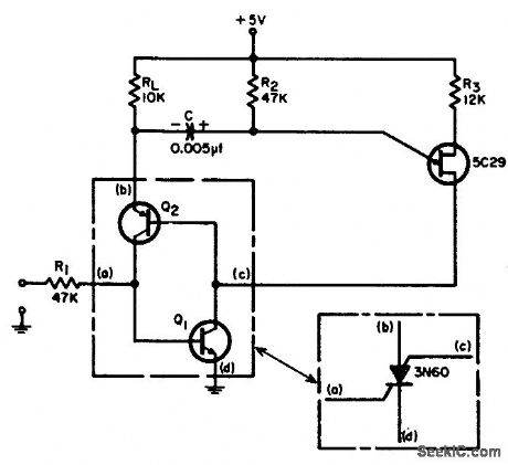
MOSSBAUER_EFFECT_SPECTROMEIER
Published:2009/7/17 2:01:00 Author:Jessie

Circuit makes effective use of transistors as current amplifiers.-W. W. MacDonald, Electronics in Israel, Electronics, 37:3, p 23-29. (View)
View full Circuit Diagram | Comments | Reading(789)
TRANSISTOR_TESTER_1
Published:2009/7/11 5:14:00 Author:May

Determlnes maxlmum frequency at which unknown transistor will still maintain reasonable current gain, and tells whethertransistor is NPN or PNP. Based on fact that emitter-base junction of transistor is equivalent to crystal diode, conducting in one direction only. Direction depends on transistor type. Setting of S2 which gives meter reading identifies transistor type. Frequency-limit circuit is self-excited oscillator in which frequency de. pends on plug-in coil. If meter reads when 60MHz coil is used, transistor is capable of handling 60 MHz; if no reading, change to lower-frequency coils one by one until reading is obtained. To check battery, press S4; lamp should have full brilliance. CR1 is 1N34A.-H. Hanson, How High Will It Go?, QST, April 1974, p 32-33 and 39. (View)
View full Circuit Diagram | Comments | Reading(1161)
GO_NO_GO_BOLTAGE_COMPARATOR
Published:2009/7/11 5:14:00 Author:May
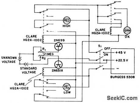
Unknown voltage is compared to standard voltage within preset voltage limits. Circuit is sensitive enough to detect 0.5 v difference.-Trcnsistor Go-No-Go Voltage Comparotor, Electronic Circuit Design Handbook, Mactier Pub. Corp. N.Y. p87. (View)
View full Circuit Diagram | Comments | Reading(652)
SELF_RESETTING_PULSE_STRETCHER
Published:2009/7/17 2:00:00 Author:Jessie
Produces output pulse that lasts for designated period of time after last of group of 20-microsec 5.v input pulses disappears. Circuit then resets, and draws no current while quiescent. Amount of stretching is determined by charging of C through R2, and is 55 microsec for values shown. Gate-turnoff scr can be used in smith, self-Resetting Pulse Stretcher, EEE, 12:8, p 71-72. (View)
View full Circuit Diagram | Comments | Reading(535)
CUTTING_NOISE_PICKUP_WITH_REMOTE_GAIN
Published:2009/7/17 2:00:00 Author:Jessie
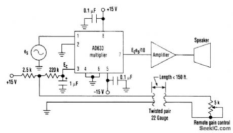
At times, gain control that is remote from the amplifier and speaker is required. However, merely extracting the gain-control potentiometer from a typical amplifier and placing it remotely will contaminate the signal with pickup. One simple solution is to use an analog multiplier as a gain-control element. The 2.5-kΩ resistor and the remote gain-control potentiometer form an attenuator of the +15-V supply, whose output is filtered through a low-pass RC filter. The resistance of the twisted pair of leads is negligible compared with the potentiometer's 5-kΩ resistance. When the remote gain-control potentiometer is at maxim Um resistance, the control voltage, Ec,at pin 3 of the multiplier is at a nominal value of + 10 Vdc. This results in a maximum input amplitude to the amplifier, which is equal to the original input signal es Correspondingly, when the gain-control potentiometer is set to zero resistance, the signal input to the amplifier is nominally zero. Any ac signals that might be picked up by the long run of wire are effectively attenuated by the large time constant of the low-pass filter. (View)
View full Circuit Diagram | Comments | Reading(618)
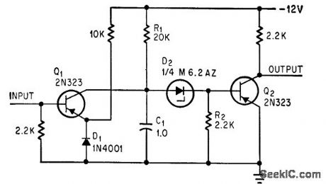
12_V_FOR_TRANSCEIVER_1
Published:2009/7/17 2:00:00 Author:Jessie
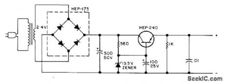
Output voltage varies only 0.2 V between transmit and receive. Transistor can be mounted directly on side of metal minibox for heatsinking. Transformer secondary is 24 V at 5 A. - Circuits, 73 Magazine, March 1977, p 152. (View)
View full Circuit Diagram | Comments | Reading(515)
DELAY_LINE_PULSE_SHAPER
Published:2009/7/17 1:59:00 Author:Jessie
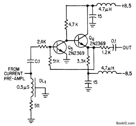
Voltage pulse from current preamplifier of multiplier photo-tube is shaped by DL1, which is shorted at one end and terminated at other end with ifs characteristic impedance, to normalize input pulse width at twice 0.5-microsec characteristic delay of line. First stage gives open-loop gain of 118. Second stage gives low-impedance drive for feedback and for following discriminator amplifier. Total loop gain is 17 for bandwidth of1 Mc.-R. Cuikay and T. Callahan, Orbiting Observatory to Measure Stars' Dim Light, Electronics, 379, p 28-31. (View)
View full Circuit Diagram | Comments | Reading(758)
5_V_AT_1_A_1
Published:2009/7/17 1:58:00 Author:Jessie
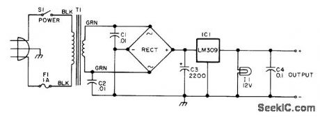
Simple lab supply provides voltage required for digital ICs Rectifier is 6-A 50-PIV bridge. Power transformer has 12.6-V secondary rated 1 A, such as filament transformer. -G. McClellan, Give That Professional Look to Your Home Brew Equipment, 73 Magazine, Feb. 1977, p 28-31. (View)
View full Circuit Diagram | Comments | Reading(552)
MAGNETIC_TAPE_SKEW_MEASUREMENT
Published:2009/7/17 1:58:00 Author:Jessie

Magnetic strip recorded on tape is scanned transversely with ring-type play-back head, and periods between output pulses generated at crossover points are measured. C1 acquires positive charge for one direction of skew and negative charge for other. Output of detector of C1, which measures this charge, is fed to difference amplifier having microammeter connected between cathodes to read tracking error.-B. R. Gooch, Magnetic Strip Keeps Tape Running True,Electronics,36:2, p42-43. (View)
View full Circuit Diagram | Comments | Reading(659)
ZENER_DIODE_PULSE_STRETCHER
Published:2009/7/17 1:57:00 Author:Jessie
Gives delays up to 50 millisec without need for large capacitance values, by varying R1; delay is 10 millisec for 20K value shown. Input is negative 1-millisec pulse, which is stretched by amount of delay.-A. S. Robin-son, Zener Diode Allows Delay Without Large Capacitors, Electronics, 39:11, p 93. (View)
View full Circuit Diagram | Comments | Reading(1079)
MAGAMP_REGULATES_2300_V_SUPPLY
Published:2009/7/17 1:56:00 Author:Jessie
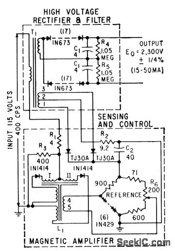
Self-saturating magnetic amplifier is placed on low-voltage input side of high-voltage 400-cps rectifier and auxiliary winding is added for output sensing, to isolate control and sensing functions from high-voltage circuit.-W. J. McDaniel and T. L. Tanner, Regulating High Voltage with Magnetic Amplifiers, Electronics, 32:29, p 64. (View)
View full Circuit Diagram | Comments | Reading(908)
| Pages:769/2234 At 20761762763764765766767768769770771772773774775776777778779780Under 20 |
Circuit Categories
power supply circuit
Amplifier Circuit
Basic Circuit
LED and Light Circuit
Sensor Circuit
Signal Processing
Electrical Equipment Circuit
Control Circuit
Remote Control Circuit
A/D-D/A Converter Circuit
Audio Circuit
Measuring and Test Circuit
Communication Circuit
Computer-Related Circuit
555 Circuit
Automotive Circuit
Repairing Circuit