
Circuit Diagram
Index 781
NTSC_RGB_VIDEO_DECODER
Published:2009/7/11 2:42:00 Author:May

An NTSC/RGB decoder is shown here. Using a TDA3330, 1-V input video is broken down into its R, G, B components, and composite synch. U1 is an integrated synch separator (LM1881). This circuit should be useful for interfacing RGB monitors to NTSC video systems. (View)
View full Circuit Diagram | Comments | Reading(3784)
809_11_KC_CLOCK_OSCILLATOR
Published:2009/7/11 2:41:00 Author:May

Crystctl-controlled oscillator V1A and shaping circuit V1B produce pulses with repetition rate equal to frequency of crystal oscillator.-H. Vantine Jr.and E. C. Johnson, Modified Transceivers Compute Distance, Electronics, 31:37, p94-98. (View)
View full Circuit Diagram | Comments | Reading(765)
REGENERATED_CW
Published:2009/7/11 2:41:00 Author:May
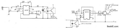
Audio oscillator whose frequency can be varied is keyed in accordance with incoming CW signal, to give clean locally generated audio signal without background noise and interference. NE567 phase-locked loop serves as tunable audio filter and LED switch driver for activating NE555 variable-frequency tone oscillator. LED serves as visual tuning aid to indicato that PLL is looked on to incoming signal.-Regenerated CW.73 Magazine, Dec. 1977,p152-153. (View)
View full Circuit Diagram | Comments | Reading(1628)
TV_LINE_PULSE_EXTRACTOR
Published:2009/7/11 2:38:00 Author:May

This circuit uses a sync-generator chip, a counter, and a decoder to detect the horizontal sync pulse that occurs at the bGginning of line 10 in field 1 of an NTSC television picture. You can use this circuit to compare the time delay between sync signals at various locations, and to determine and correct for any drift between the two master clocks.The output of the LM1881 sync separator is the key to detecting line 10; the odd/even line goes high on the leading edge of the first equalizing pulse in the middle of line 4. Thus, you can use this knowledge to find virtually any other line in the field. This particular circuit locates line 10 of field one. The circuit resets the 74LS161 counter until the odd/even line goes high. Then, 74LS161 counts the positive transitions of the sync signal. After 11 positive transitions, the sync pulse drives pin 4 of the 74LS138 decoder low, and the line-10 sync pulse appears at pin 12 of the decoder. (The circuit counts to 11, as opposed to the 6 you might expect-because the composite sync signal contains more than 1 pulse per line). The counter remains in its maximum-count state until the sync separator causes a reset because Q1 feeds the inverted terminal-count output back to the parallel-enable input. (View)
View full Circuit Diagram | Comments | Reading(1932)
SIDETONE_MONITOR
Published:2009/7/11 2:38:00 Author:May

Mostek MK5086N IC is used with crystal in range from 2 to 3.5 MHz as signal generator driving FET audio amplifier.Switch S1 gives choice of four AF tones, determined by dividing crystal frequency in hertz by 5120 for T1, 4672 for T2, 4234 for T3, and 3776 for T4. Can also be used as code practice set and as audio signal generator.-J. Garrett, A Sidetone Monitor-Oscillator-Audio Generator, QST, June 1978, p 43. (View)
View full Circuit Diagram | Comments | Reading(1734)
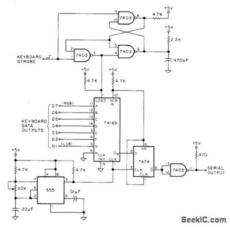
PARLLEL_TO_SERIAL_CONVERSION
Published:2009/7/11 2:37:00 Author:May

Can be used as interface between parallel outputs of keyboard and serial input port of microprocessor. Keyboard output data is fed to 74165 shift register, with eighth input tied low. 7403 gates are connected as mono MVBR for converting keyboard strobe to narrow pulse for loading shfft register. Fourth gate in package serves as output buffer. 555 timer forms clock adjustable from 150 to 1400 Hz, to allow operational standard baud rates of 150, 300, 600, or 1200.-F. J.Greeb, Who Needs a UART?, Kilobaud, Aug.1978, p 108. (View)
View full Circuit Diagram | Comments | Reading(2677)
CLOCK_PULSE_GENERATOR
Published:2009/7/11 2:37:00 Author:May

Derives pulse from reading head that scans data track of magnetic-spoke disk memory, eliminating need for separate timing track. Generates pulse for each magnetic spoke passing over gap of head, regardless of whether spoke is written with 1 or 0.-T. C. Chen and O. B. Stram, Digital Memory System Keeps Circuits Simple, Electronics, 32:11, p130-133. (View)
View full Circuit Diagram | Comments | Reading(776)
PHASE_SYNCHRONIZER
Published:2009/7/11 2:33:00 Author:May
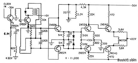
Used to synchronize 2,500-cps local time standard with that of transmitting end of wire-line system. When zero crossings of pulses do not coincide, error signal is produced which, after amplification, is applied to motor that rotates phase shifter until there is phase synchronization between local clock and incoming information.This insures sampling of recovered information at middle of incoming bit.-J.L.Hollis, Sending Digital Data Over Narrow-Band Lines, Electronics, 32:23, p72-74. (View)
View full Circuit Diagram | Comments | Reading(851)
RGB_NTSC_CONVERTER
Published:2009/7/11 2:31:00 Author:May

Using a Motorola MC1377, this circuit produces NTSC video from an RGB source. Components are not critical, except for R7 and CB, which should be 1% and 2% tolerance. respectively. (View)
View full Circuit Diagram | Comments | Reading(3912)
CQ_CALL_SYNTHESIZER
Published:2009/7/11 2:31:00 Author:May
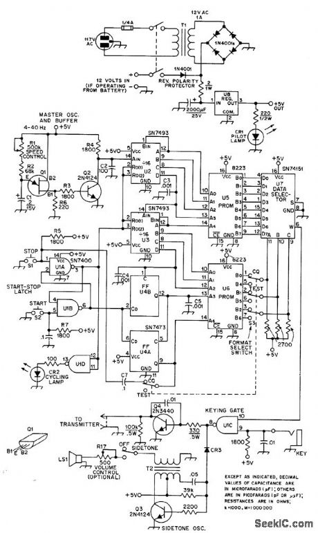
Uses only two Signetics 8223 256-bit PROMs for storing up to 2048 bits of code information, for automatic generation of Morse-code CQ calls, test messages, and other frequently used messages. Repeated words are stored in only one location and selected as needed, to quadruple capacity of memory. PROMs can be programmed in field or custom-programmed by manufacturer.Speed and timing of code characters are deter.mined by UJT oscillator 01, variablefrom about 4 to 40 Hz or 5 to 50 WPM. CR1 and CR2 are Archer (Radio Shack) 276-042 orequivalent. CR3 is 1N34A, 1N270, or equivalent germanium. Q1 is Motorola MU4891 or equivalent. Article describes circuit operation and programming in detail-J. Pollock, A Digital Morse Code Syn thesizer, QST, Feb. 1976, p 37-41. (View)
View full Circuit Diagram | Comments | Reading(943)
TRANSISTOR_CURVE_TRACER
Published:2009/7/11 2:31:00 Author:May

When fed with staircase waveform of base-culrent generator, circuit generates series of current-voltage (I-V) curves as function of base current, for transistors and other three-terminal semiconductor devices. Cathodefollower U5 and inverting controlled-gain amplifier U6 can be eliminated if correct sense of current indication is not essential. S11 switches multiplier R9 in and out; R9 is 18 megohms (about 9 times input resistance of CRO). C1 is 7-13 pF mica trimmer. Diodes are 1N4822. U5 and U6 are Fairchild 741. T2 is Knight 54A3800 or equivalent variable autotransformer rated 1 A. T3 is Knight 54A141O or equivalent power transformer with 125-V 15-mA and 6.3-V 0.6-A secondaries.-R. P. Ulrich, A Semiconductor Curve Tracer for the Amateur, QST, Aug. 1971, p 24-28. (View)
View full Circuit Diagram | Comments | Reading(4544)
TRANSISTOR_PIN_FINDER
Published:2009/7/11 2:29:00 Author:May

Simple audio oscillator is assembled as shown and values of R1 and C1 adiusted for desired tone. General-purpose transistor to be tested is then substituted in circuit (NPN for Q1 or PNP for Q2) and rotated in socket until oscillator works again; pins then correspond to those of the good transistor. If oscillator will not work in any of three possible positions, transistor under test is bad.-Circuits, 73 Magazine, July 1977, p 34. (View)
View full Circuit Diagram | Comments | Reading(3951)
_VIDEO_A_D-D_A_CONVERTER
Published:2009/7/11 2:29:00 Author:May

This circuit is useful for digital video experiments and for interfacing video with a computer that has a TDA8708 (Philips). The A/D converter provides 8-bit digitized video to k23 socket and k21 socket. A TDA8702 (Philips) D/A converter recovers analog video. IC3 is a 1- to 5-ms delay line (1505) to delay clock pulses in 1-ms steps to the DiA converter. Clock speeds can be up to 30 MHz. Three video inputs are provided for three analog channels (e.g., R, G, B video). (View)
View full Circuit Diagram | Comments | Reading(1955)
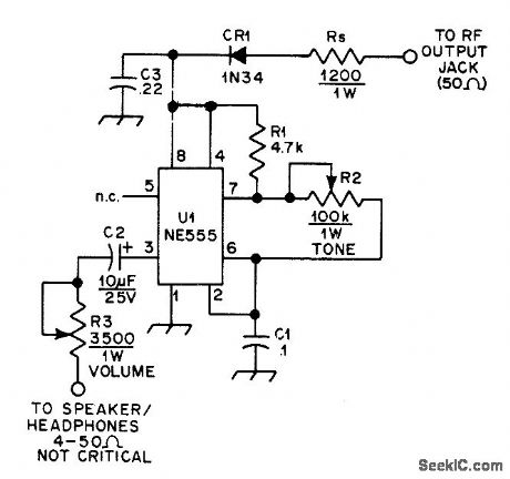
AF_OSCILLATOR_MONITORS_CW
Published:2009/7/11 2:29:00 Author:May


Can be added to any transceiver not already having built-in sidetone oscillator, to hear keying of transmitter. RF input from transmitter is rectified by CR1 to provideabout 6-VDC supply. Keying of carrier on and off tums NE555 AF oscillator on and off correspondingly.-J. Amold, A CW Monitorfor the Swan 270, QST, Aug. 1976, p 44. (View)
View full Circuit Diagram | Comments | Reading(1100)
IC_TEST_CLlP
Published:2009/7/11 2:28:00 Author:May

Provides in-circuit testing for all types of 16-pin ICs. LED array indicates logic status of each IC pin. Circuit uses Texas Instruments TID125 diode arrays on test clip to determine pin with highest voltage (VCC)and pin with lowest voltage (GND). These pins are then used to supply power to LEDs. No batteries are needed. Position of clip on IC is unimportant. On 14-pin ICs, disregard LEDs for two unused pins. Circuit can be expanded for 24- or 40-pin ICs, although adding LEDs makes clip more difficult to use.-J. Errico and R. Baker, Powerless IC Test Clip, BYTE, Dec. 1975, p 26-27. (View)
View full Circuit Diagram | Comments | Reading(1993)
SENSOR_KEYER
Published:2009/7/11 2:28:00 Author:May
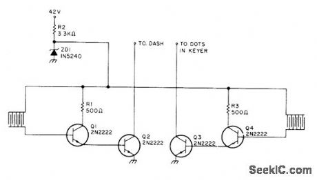
Skin resistance of about 10k creates dashes when finger touches grid pattern on left side of paddle and dots when other finger touches pattern on other side. Transistors act as solid-state switches. Developed for use with Heathkit CW keyer HD-10. Supply is 10V, obtained from 10-V zener connected through appropriate dropping resistor to higher-voltage source. Article covers construction of paddle by etching printed-wiring board.-T. Urbizu, Try a Sensor Keyer, 73 Magazine, Jan. 1978, p 184-185. (View)
View full Circuit Diagram | Comments | Reading(1356)
SETTING_CLOCK_TO_WWV
Published:2009/7/11 2:27:00 Author:May
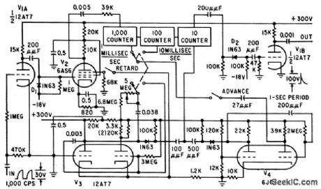
Locally genemted pulses can be easily synchronized with pulses from WWV to see clocks associated with frequency standard. Changes in period of pulses from counter-type frequency dividers are made with precision vernier. Any 10-stable divider can be used in counler circuit.-E. F.Wilson, Using Divider Vernier to Synchronize Pulses, Electronics, 32:27,p44-45. (View)
View full Circuit Diagram | Comments | Reading(644)
KEYBOARD_FOR_PROM
Published:2009/7/11 2:26:00 Author:May
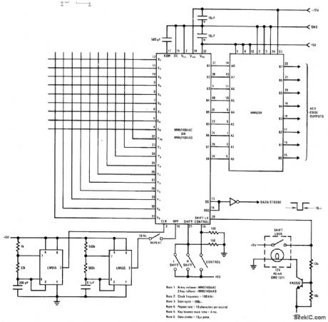
National MM5740 encoder serves as interface between keyboard and MM5204 4K PR0M capable of handling 90 four-mode keys. Encoder includes all Iogic needed for key validation, two-key or N-key rollover, bounce masking, mode selection, and strobe generation. Key code outputs can be defined by user. Bit-paired coding system of en coder has five common bits (B1-B4 and B9) and four variable bits (B5-B8) for each key. Each keyswitch is defined by one X drive line and one Y sense line of encoder,Combinationgives totalof 360 9-bit codes,-''Memory ApplicationsHandbook,'' National Semiconductor,SantaClara,CA,1978,p 5-⒌-5-8.
(View)
View full Circuit Diagram | Comments | Reading(983)
35_W_FOR_CW
Published:2009/7/11 2:24:00 Author:May
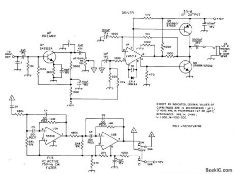
Discrete devices minimize distortion and eliminate fuzziness while listening to low-level CW signals in communication receiver covering 1.8-2 MHz. RC active bandpass filter peaked at 800 Hz improves S/N ratio for weak signals. Adiust BFO of receiver to 800 Hz.Two-part article gives all other circuits of recelver,-D.DeMaw,His Eminence-the Receivel,OST, Part 2-July 1976,p 14-17(Part 1-June 1976,p 27-30), (View)
View full Circuit Diagram | Comments | Reading(902)
CATHODE_COUPLED_MAIN_GATE_MVBR_1
Published:2009/7/17 3:34:00 Author:Jessie
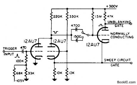
Provides positive unblanking gate. Used in radar to provide gate during which display sweep is generated. Capacitor switching provides choice of pate lengths.-NBS, Handbook Preferred Circuits Navy Aeronoutical Electronic Equipment, Vol. 1, Electron Tube Circuits, 1963, p N10-2. (View)
View full Circuit Diagram | Comments | Reading(620)
| Pages:781/2234 At 20781782783784785786787788789790791792793794795796797798799800Under 20 |
Circuit Categories
power supply circuit
Amplifier Circuit
Basic Circuit
LED and Light Circuit
Sensor Circuit
Signal Processing
Electrical Equipment Circuit
Control Circuit
Remote Control Circuit
A/D-D/A Converter Circuit
Audio Circuit
Measuring and Test Circuit
Communication Circuit
Computer-Related Circuit
555 Circuit
Automotive Circuit
Repairing Circuit