
Circuit Diagram
Index 794
Ramp_and_hold
Published:2009/7/17 3:49:00 Author:Jessie
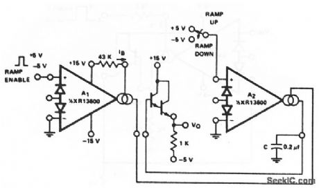
This circuit uses both sections of an XR-13600(Fig.11-1B). The circuit Sources IB into capacitor C whenever the input to A1 is made high,giving a ramp rate of about 1V/ms for the values shown.EXAR corporation Databook 1990 p 5-257 (View)
View full Circuit Diagram | Comments | Reading(709)
WATCH_CRYSTAL_TIMER
Published:2009/7/10 23:30:00 Author:May

When used withstandard 4.194-MHz watch crystal, Intersil 7213 crystal-controlled timer generates outputs of 1 pulse per second and 1 pulse per minute,using internal divider chain CMOS dynamic and static dividers keep power dissipation under 1 mW with 5-V supply,-B.O'Neil,IC Timers-the Old Reliable 555 Has Company,EDN Magazine, Sept 5,1977,p 89-93, (View)
View full Circuit Diagram | Comments | Reading(790)
MODEL_TRAIN_TRACK_CONTROL_SIGNAL
Published:2009/7/17 3:47:00 Author:Jessie

The circuit is based on a 555 timer IC, U1, and operates on 5-Vdc to make it usable with digital logic. The operating power of the circuit can be converted to 12 V by increasing the values of R2 and R3. Train detection is accomplished by photocell PC1, which should be mounted between the rails, flush with or slightly below the ties. A small light must be mounted directly above PC1 when it is used in a dark area. Resistor R4 is adjusted so that when a train covers PC1, the circuit triggers. Resistor R1 reduces the current to U1 if R4 is set for minimum resistance. Variable resistor R4 can also be ad-justed so that each individual car in a train will change the colors of LED1, a bicolor unit, back and forth, indicating train movement. That can be handy if two circuits are used, one at each end of the track block. It will indicate that the train has begun to move, Mount LED1 on the control panel. The circuit is designed to indicate a green when no train is present. When a train covers PC1, U1 switches LED1 to red, indicating that the train is in position. (View)
View full Circuit Diagram | Comments | Reading(1395)
CLOCK_FOR_MC6800
Published:2009/7/10 23:29:00 Author:May

Produces nonoverlapping complementary 5-V clock outputs as required for phase 1 and phase 2 clock inputs of microprocessor. Oscillator can be any source having maximum frequency of 1 MHz with TTL Ievels and 50% duty cycle, such as Motorola K1100A. MC3000 and MC3001 TTL gates are chosen for their speed and drive characterlstics.All transistors are MPQ6842.- Microprocessor Applications Manual (Motorola Series in Solid-State Electronics), McGraw-Hill, New York, NY 1975, p 4-1-4-6. (View)
View full Circuit Diagram | Comments | Reading(1283)
20_kHz_nicad_battery_charger_with_voltage_sensing
Published:2009/7/17 3:47:00 Author:Jessie

20 kHz nicad battery charger with voltage sensing (courtesy Motorola Semiconductor Products Inc.). (View)
View full Circuit Diagram | Comments | Reading(666)
GATE_TURNOFF_CHOPS_28V_AT_1OO_KC
Published:2009/7/10 23:29:00 Author:May

Saturctble transformer and gate turnoff scr give simple 100-kc chopper in which potentiometer R2 controls on-to-off timer.-D.R. Grafham, Now the Gate Turnoff Switch Speeds Up D-C Switching, Electronics, 37:12, p64-71. (View)
View full Circuit Diagram | Comments | Reading(469)
GRAND_PRIX_STARTING_LIGHTS_
Published:2009/7/17 3:46:00 Author:Jessie

The figure shows a circuit design for a starting gantry with three red and three green starting lights. It can be powered from the racing set's power-supply unit. A 12-V regulator (IC1) provides a stabilized supply for the circuit and diode D1 prevents accidental reverse connection by the young motor enthusiast. The circuit uses a system of relays to start and stop the sequence. When START switch S1 is pressed, relay contacts RLA1 close and this applies +12 V to the sequencer and also latches the relay. Contacts RLA2, across capacitor C3, open. Three comparators are used (IC2a, IC2b, and IC2c), and their noninverting (+) terminals each have a reference voltage set by a potential divider at about +2.10 V, +2.75 V, and +4.75 V, respectively. Either an LM339 quad comparator or an LM324 quad op amp can be used. When capacitor C3 charges in excess of +1.75 V, transistor TR1 conducts and the red LEDs D4 to D6 illuminate. At +2.75 V, TR2 conducts and the green LEDs D7 to D9 light. IC2a also swings high, via resistor R6, and so the red lamps extinguish. When capaci-tor Ct reaches +4.75 V, transistor TR3 conducts and completes the circuit to relay RLB. Contacts RLB1 (normally closed) now open and disconnect relay RLA. Contacts RLA2 then close, which dis-charges the timing capacitor C1, ready for next time. (View)
View full Circuit Diagram | Comments | Reading(1013)
TELEPHONE_LINE_IN_USE_INDICATOR
Published:2009/7/10 23:29:00 Author:May

When a telephone line is not in use, about 48 V appears across the line, which drops to about 10 V or less when the line is in use. This circuit switches a bicolor LED as an indicator. (View)
View full Circuit Diagram | Comments | Reading(1022)
1_Hz_CLOCK_WITH_BATTERY_BACKUP
Published:2009/7/10 23:28:00 Author:May

Circuit normally produces output pulses at 1-s intervals with basic accuracy corresponding to that of power-line frequency. Programmable 8260 timer operates as divide-by-60 counter produc ing output swing compatible with TTL or 5-V CMOS loads. With backup power applied to OR gate D1-D2, circuit operates reliably at 1 s over supply range of 5-15 V. Power drain is minimized at ±5 V.-W. G. Jung, IC Timer Cookbook, Howard W. Sams, Indianapolis, IN, 1977, p 214-215. (View)
View full Circuit Diagram | Comments | Reading(1177)
V_F_CONVERTER_FOR_TRANSDUCER
Published:2009/7/10 23:27:00 Author:May

Output of low-level transducer such as temperature bridge can be transmitted reliably over long wires (100feet or more) in serial form if changes in 100-ohm resistive thermal device (RTD) are converted to corresponding changes in frelquency with almost any commercially available V/F converter, Typical converter has 0-10 V fullscale analog input and 0-10 kHz output. If 5 V is applied to input, output pulse train will have rate of 5 kHz ±0.5 Hz, which can be counted for 1 s or less and displayed on digital readout to show analog value Instrument amplifier can be Datel AM201 or equlvaient.-E. L. Murphy,Sending Transducers Signals over 100 Feet?,Instuments Control & Systems,June 1976,p 35-39. (View)
View full Circuit Diagram | Comments | Reading(918)
Peak_detector_and_hold
Published:2009/7/17 3:45:00 Author:Jessie
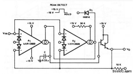


This circuit uses both sections of an XR-13600 (Fig. 11- 1B). The peak detector uses A2 to turn on A1 whenever VIN becomes more positive than VO. A1 then charges C to hold VO equal to VIN (peak). Notice that the Darlington used must be on the same side of the package as A2 because the Ay Darlington is turned on and off with A1. Pulling the output of A2 low through D1 serves to turn off A1 so that VO remains constant. EXAP Corporation Databook 1990 p 5 257 (View)
View full Circuit Diagram | Comments | Reading(769)
TELEPHONE_MESSAGE_TAKER
Published:2009/7/10 23:27:00 Author:May

This circuit operates on the ringing voltage of the telephone to trigger a tape recorder to record messages. K1 can be made to latch using extra contacts if the tape recorder requires a constant-contact closure. (View)
View full Circuit Diagram | Comments | Reading(905)
NORMALLY_ON_GTO_CHOPPER
Published:2009/7/10 23:25:00 Author:May

Small trigger at input removes applied voltage from load for duralion of time constant R2-C1. Handles 1kw at 1 kc.-J. W. Motto, Jr, Swilching Circuits Using the Gate Turnoff Controlled Rectifier, EEE, 11:3, p.52-55. (View)
View full Circuit Diagram | Comments | Reading(443)
REMOTE_RINGER
Published:2009/7/10 23:24:00 Author:May

A telephone bell circuit usmg a Motorola MC34017 can be built from a few components. C1 and UI depend on the type of nng required.U1 C1 RingMC34017-1 1 000 pF 1 kHzMC34017-2 500 pF 2 kHZMC34017-3 2 000 pF 500 HzSelect the verslon of MC34017 and C1 from this table. (View)
View full Circuit Diagram | Comments | Reading(856)
12_volt_battery_charger_with_an_SOB_and_a_PUT_
Published:2009/7/17 3:44:00 Author:Jessie

12-volt battery charger with an SOB and a PUT (courtesy Motorola Semiconductor Products Inc.). (View)
View full Circuit Diagram | Comments | Reading(1033)
Sample_hold
Published:2009/7/17 3:44:00 Author:Jessie

Although only one section is shown, this sample/hold circuit requires that the Darlington buffer be used from the other half of the package, and that the corresponding amplifier be biased on continuously. EXAR Corporation Databook, 1990, p 5-257. (View)
View full Circuit Diagram | Comments | Reading(632)
±1K_ACCURACY_FOR__55_to_+125℃
Published:2009/7/10 23:23:00 Author:May

Matched transistor pairs and opamps give highv accuracy temperature-measuring system that is easy to calibrate, has long-term stability, and can operate with sensor transistor pair up to 100 feet from rest of circuit. Common-mode rejection at amplifier input is greater than 100 dB. Output voltage is +2.18V at-55℃ (218 K), increasing to +3.98 V at +125℃(398 K).-J. Simmons and D. Soderquist, Temperature Measurement Method Requires No Referencd,EDN Magazine, Aug. 5, 1974, p 78 and 80. (View)
View full Circuit Diagram | Comments | Reading(681)
ONE_CHIP_FRONT_END_AM_RECEIVER
Published:2009/7/17 3:43:00 Author:Jessie

The schematic diagram of the receiver circuit is shown. About all you have to do is wind two coils, connect a few components together, and tie the input to a simple wire antenna, and a receiver is born. The two coils, L1 and L2, each comprised 100 turns of #28 enamel-covered copper magnet wire wound on T80-2 toroid cores (with a tap at the 30th turn on L1). (View)
View full Circuit Diagram | Comments | Reading(1987)
320_kHz_FOR_CALCULATOR
Published:2009/7/10 23:22:00 Author:May


Two low-cost TTL ICs generate 320-kHz clock signals for electronic desk calculator, Output swings between +7.2 V and -7.2 V. NAND gates of ICs are connected to form free-running multivibrator, with self-starting gate C ensuring that clock waveform is availableas soon as supply voltage is applied.-T. J. Terrell, Clock Generator for Electronic Calculators, Wireless World, Dee. 1975, p 575. (View)
View full Circuit Diagram | Comments | Reading(1557)
Automotive_regulated_battery_charger
Published:2009/7/17 3:42:00 Author:Jessie

Automotive regulated battery charger. Adjust R1 for a fully charged battery voltage. This inexpensive unit can charge any 12-volt lead-add battery. Should the battery become discharged while the charger is connected the unit will come back on again to recharge the battery (courtesy General Electric Company). (View)
View full Circuit Diagram | Comments | Reading(672)
| Pages:794/2234 At 20781782783784785786787788789790791792793794795796797798799800Under 20 |
Circuit Categories
power supply circuit
Amplifier Circuit
Basic Circuit
LED and Light Circuit
Sensor Circuit
Signal Processing
Electrical Equipment Circuit
Control Circuit
Remote Control Circuit
A/D-D/A Converter Circuit
Audio Circuit
Measuring and Test Circuit
Communication Circuit
Computer-Related Circuit
555 Circuit
Automotive Circuit
Repairing Circuit