Amplifier Circuit
Peak_detector_and_hold
Published:2009/7/17 3:45:00 Author:Jessie | From:SeekIC


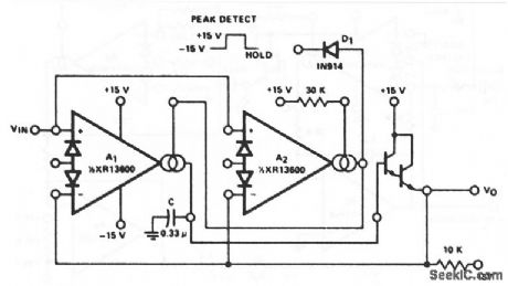
This circuit uses both sections of an XR-13600 (Fig. 11- 1B). The peak detector uses A2 to turn on A1 whenever VIN becomes more positive than VO. A1 then charges C to hold VO equal to VIN (peak). Notice that the Darlington used must be on the same side of the package as A2 because the Ay Darlington is turned on and off with A1. Pulling the output of A2 low through D1 serves to turn off A1 so that VO remains constant. EXAP Corporation Databook 1990 p 5 257
Reprinted Url Of This Article:
http://www.seekic.com/circuit_diagram/Amplifier_Circuit/Peak_detector_and_hold.html
Print this Page | Comments | Reading(3)

Article Categories
power supply circuit
Amplifier Circuit
Basic Circuit
LED and Light Circuit
Sensor Circuit
Signal Processing
Electrical Equipment Circuit
Control Circuit
Remote Control Circuit
A/D-D/A Converter Circuit
Audio Circuit
Measuring and Test Circuit
Communication Circuit
Computer-Related Circuit
555 Circuit
Automotive Circuit
Repairing Circuit
Code: