
Circuit Diagram
Index 796
12_15_V_AT_500_W
Published:2009/7/17 3:36:00 Author:Jessie

Developed to permit operation of high-power mobile solid-state amateur transmitter in home. Current sensing is done with 15-milliohm resistor R16. Short-circuit cutoff is provided by regulator along with current limiting through R16. Output voltage begins dropping as load exceeds 35 A. When voltage drops below 8 V, Q1 turns off and SCR1 turns on, cutting output power. Power supply must be turned off to unlatch SCR1. For over-voltage shutdown, CR2 starts conducting above 16 V, turning on SCR2 and activating relay K1 to cut off main DC supply. Article gives construction details. T1 has 22-V secondary.-C. C. Lo, 500-Watt Regulated Power Supply, Ham Radio, Dec. 1977, p 30-32. (View)
View full Circuit Diagram | Comments | Reading(910)
TESLA_COIL_SECONDARY_RECEIVER
Published:2009/7/17 3:36:00 Author:Jessie

Here's a Tesla-coil secondary to try: Wind 750 turns of 24-gauge enameled magnet wire onto an 18 long piece of 1.9 outer-diameter PVC pipe. The large coil has an inductance of about 2800 mH, with a self-capacitance of about 20 pF. One end of the coil should be earth grounded. Put a metal ball (a drawer pull knob or doorknob) at the other end. Now attach it to a crystal radio.The RF is detected by a 1N34 germanium diode, D1, and you will note that signal strength is high. What you should hear is one or possibly several AM radio stations, depending on the coil, the radio frequencies in your area, and distance to the transmitter(s). (View)
View full Circuit Diagram | Comments | Reading(2109)
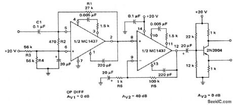
Servo_motor_preamplifier_3
Published:2009/7/17 3:35:00 Author:Jessie

Servo motor preamplifier (courtesy Motorola Semiconductor Products Inc.). (View)
View full Circuit Diagram | Comments | Reading(514)
Servo_motor_preamplifier_2
Published:2009/7/17 3:34:00 Author:Jessie
Servo motor preamplifier (courtesy Motorola Semiconductor Products Inc.). (View)
View full Circuit Diagram | Comments | Reading(571)
RECEIVER_FRONT_END_SELECTOR
Published:2009/7/17 3:34:00 Author:Jessie

Receiver front-end selection can be accomplished by using PIN-diode switches (as shown). The PIN diodes can be MV3404 or similar types. (View)
View full Circuit Diagram | Comments | Reading(580)
Phase_locked_loop
Published:2009/7/17 3:34:00 Author:Jessie
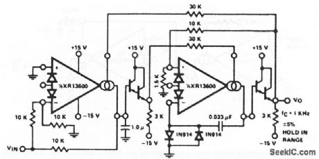
This PLL uses the four- quadrant multiplier (Fig. 11-4) and VCO (Fig.11-16).The circuit has a ±5% hold- in range and an input sensitivity of about 300 mV EXAS corporation Databook 1990 p 5-256 (View)
View full Circuit Diagram | Comments | Reading(0)
TELEPHONE_AMPLIFIER
Published:2009/7/10 23:11:00 Author:May
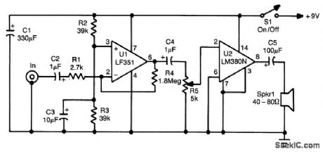
This amplifier can be used in telephone work or where a simple speech amplifter is required. The frequency response can be varied by the value of C2. C4. and addition of a capacitor across R4 ( ≈ 33 pF for voice band) to limit the HF response. (View)
View full Circuit Diagram | Comments | Reading(0)
PHONE_IN_USE_INDICATOR
Published:2009/7/10 23:08:00 Author:May

The circuit receives its power from a 15-V wall adapter (not shown). The circuit takes advantage of the fact that the phone line voltage drops from 48 to 10 V when an extension is taken off the hook. When the voltage on a line drops, the optoisolator/coupler is turned off so that the inputs to the line-1 hexinverters (U2 pins 1. 3. and 5) float high. The corresponding outputs (U2 pins 2. 4. and 6) go low and light the line-1 LEDs. (View)
View full Circuit Diagram | Comments | Reading(1146)
MULTITRACE_CRO_DISPLAY
Published:2009/7/10 23:06:00 Author:May

Allows simullaneous presentaion of desired pulse and of limit voltage levels Choppers operate 45°out of phase, which Provides approximately equal brightness for both parts of display.-D F.Frost and R. M. Zilberstein, Multitrace Display Device, EEE, 10:8, p27. (View)
View full Circuit Diagram | Comments | Reading(654)
NORMALLY_OFF_GTO_CHOPPER
Published:2009/7/10 23:01:00 Author:May

Small trigger at input generates high.power pulse with duration determined by time constant R2-C1.Gate-turnoff controlled recliner in this circuit will chop 1 kw at 1 kc.-J.W. Motto, Jr, Switching Circuits Using the Gate Turnoff Controlled Rectifier, EEE, 11:3, p52-55. (View)
View full Circuit Diagram | Comments | Reading(538)
SERVOED_SHIELD_FOR_PROBE
Published:2009/7/10 22:59:00 Author:May

Used when only part of temperature sensor can touch surface being measured. LM195H powertransistor is main power amplifier and at same time serves as 23-W heater that is used to make copper shield track actual temperature of surface to be measured. Uses National LX5700 sensors. Diode in series with ground leg of one sensor permits adjusting pin 3 of that sensor over range of 40-80 mV to make it track with servo thermometer. Digital voltmeter is used to read temperature directly in degrees C.-P. Lefferts, A New Interfacing Concept; the Monolithic Temperature Transducer, National Semiconductor, Santa Clara, CA, 1975, AN-132, p 6. (View)
View full Circuit Diagram | Comments | Reading(588)
VARIABLE_WIDTH_AND_PRF
Published:2009/7/10 22:59:00 Author:May

Low-cost pulse generator uses versatile dual monostable IC to provide clock pulses that gan be varied in width over wide range bv changing sizes of two extemal capacitors and adiusting 47K linear pots.Switched bank of six capacitors can be used instead, to give on or off times ranging between 100 ms and 100 ns, asgiven in table. With switch in external position, on-time mono is driven by three transistors connected as Schmitt trigger giving pulse having same trequency as that of input signal. VR1 sets trigger level. Suitable regulated 5-V supply circuit is also shown,-J. Garrett, Pulse Generator, Wireless Workl, Feb.1976,p78. (View)
View full Circuit Diagram | Comments | Reading(628)
TELEPHONE_VISUAL_RING_INDICATOR
Published:2009/7/10 22:58:00 Author:May

This circuit will indicate the receipt of a call. When the telephone rings,a 100- to 120-V ring signal breaks over NE1, and causes SCR1 to trigger. This causes LED1 to light until the SCR1 is turned off by depressing S1 (View)
View full Circuit Diagram | Comments | Reading(734)
VOLTAGE_REFERENCE_TH_ERMOM_ETER
Published:2009/7/10 22:58:00 Author:May

Pre-cision Monolithics comparator CMP-02 tums on heating-element driver Q1 when temperature drops below set point determined by ratio of R1 to R2, as sensed by +5 V voltage reference REF02 serving as thermometer. Circuit also provides adjustable hysteresis, determined by R6 and R7, if this feature is desired. Values in parentheses are for 60℃ set point. REF-02 should be thermally connected to substance being heated. Design equations are given.- Linear & Conversion I.C. Products, Precision Monolithics, Santa Clara, CA, 1977-1978, p 15-4. (View)
View full Circuit Diagram | Comments | Reading(996)
GLITCH_CORRECTOR
Published:2009/7/10 22:58:00 Author:May

Circuit shown prevents TTL devices from seeing two clock pulses when output of 555 timer has glitch on falling edge atabout 0.8 V.-J Magee,Glitch,73 Magazine, Jan 1976, p10. (View)
View full Circuit Diagram | Comments | Reading(647)
JONES_CHOPPER_FOR_BATTERY_POWERED_VEHICLE
Published:2009/7/10 22:58:00 Author:May

Uses variable-frequency constant pulse-width system that starts reliably and provides smooth acceleration. At low speeds, on time of chopper, in series with d-c series motor,is much less than off time so average motor voltage is low. Potentiometer R2 controls ratio of on to off limes for speed control. Silicon Controlled Rectifier Manual, Third Edition, General Electric CO,1964, p173. (View)
View full Circuit Diagram | Comments | Reading(1552)
CENTERING_CLOCK_SIGNAL
Published:2009/7/10 22:58:00 Author:May

Circuit generates DC bias across complementarv outputs of Motorola MC10131 flip-flop for optimum operation with emitter-coupled logic (10,000 series).Bias is independent of state of flip-flop, which uses toggle frequency of about 150 MHz. Article covers applications for other flip-flops and counters requiring maintenance of best toggle frequency over wide temperature range.-T.Balph and H. Gnauden, Build a Clock Bias Circuit for ECL Flip-Flops, EDN fllagazine, May 5, 1976, (View)
View full Circuit Diagram | Comments | Reading(1160)
BRIDGE_TYPE_SENSOR
Published:2009/7/10 22:56:00 Author:May
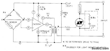
CA3094 programmable opamp is connected as level-triggered MVBR at output of bridge, driving triac for temperature monitor or control applications. Sensor can be any temperatu re-depend ent device. Load can be lamp, horn, or bell. For control applications, load is appropriate temperature-controlling device connected in feedback relationship to sensor.- Circuit Ideas for RCA Linear 'ICs, RCA Solid State Division, Somerville, NJ, 1977, p 10. (View)
View full Circuit Diagram | Comments | Reading(1103)
PRINTED_CIRCUIT_CHOPPER
Published:2009/7/10 22:54:00 Author:May

Uses convenlional Bright chopper connected to reference supply through coupler, constructed on ceramic chip. Q1 and Q4 are 2N914 matched pairs, Q2 and Q3 ore 2N2412, and Q5 and Q6 are 2N914. All diodes are IN914.-D.D. Robinson, Application of Integrated Circuits: An Evolutionary Approach, EEE, 12:4, p 42-47. (View)
View full Circuit Diagram | Comments | Reading(556)
CLOCK_WITH_REFRESH_CONTROLS
Published:2009/7/10 22:54:00 Author:May


Crystal-stabilized 1-MHz clock source such as Motorola K1100A produces complementary 5-V clock outputs required for phases 1 and 2 of MC6800 MPU and also provides interface signals required for dynamic (refresh request and refresh grant) and slow (memory ready) memories. Refresh control circuit uses MC7479 dual latch, MC7404 hex inverter, and pair of 10K pull-up resistors. If ref resh request state is low when sam pled during leading edge of phase 1, phase 1 is held high and phase 2 low for at least one full clock cycle. Refresh grant signal is high to indicate to dynamic memory system that refresh cycle exists. If memotry ready line is low when sampled on leading edge of phase 2, phase 1 is held low and phase 2 high until memory ready line is brought high by slow memory controller.All transistors are MP06842.- Microprocessor Applications Manual (Motorola Series in SolidState Electronics), McGraw-Hill, New York, NY, 1975, p 4-57-4-58. (View)
View full Circuit Diagram | Comments | Reading(699)
| Pages:796/2234 At 20781782783784785786787788789790791792793794795796797798799800Under 20 |
Circuit Categories
power supply circuit
Amplifier Circuit
Basic Circuit
LED and Light Circuit
Sensor Circuit
Signal Processing
Electrical Equipment Circuit
Control Circuit
Remote Control Circuit
A/D-D/A Converter Circuit
Audio Circuit
Measuring and Test Circuit
Communication Circuit
Computer-Related Circuit
555 Circuit
Automotive Circuit
Repairing Circuit