
Circuit Diagram
Index 798
TELEPHONE_SILENCER
Published:2009/7/10 22:34:00 Author:May
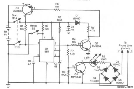
If you are busy and cannot answer or do not wish to answer your phone, this circuit will give a busy signal without you having to leave the phone off the hook. After a predetermined time, the circuit is deactivated. U1 forms an astable multivibrator that can be set for a time up to 10 minutes by values of R3 and C3. When S1A is depressed, U1 starts, and Q1 latches, which powers the circuit. At the end of a time interval determined by R3 and C3, Q2 and Q3 cut off and remove power from the circuit. During the operation, 53 throws a 150-Ω resistor across the phone line, which simulates an off-hook condition. (View)
View full Circuit Diagram | Comments | Reading(1298)
DEFLECTION_PLATE_AMPLIFIEB
Published:2009/7/10 22:34:00 Author:May

Resistive colllector network of symmetrical differentrial amplifieris replaced by constant-current source to improve slew rate of deflection amplifier driving capacitive load such as deflection plates of electrostatic cathode-ray tube.Q1 and Q2 are idetical current sources,Network Q1-CR1-Q7-R6-R8 forms current source for Q1, Q7, is used as 6.2-V zener diode,-W Peterson,Current Sources lmprove Amplifier Slew Rate,EEE Magazine, Nov,1970、p102. (View)
View full Circuit Diagram | Comments | Reading(2310)
ASYNCHRONOUS_SQUARE_WAVE_CHOPPER
Published:2009/7/10 22:31:00 Author:May


Used to interrupt or chop square wave gen orated with or in between regular system clock pulses, at specified times. Clock pulses are applied to bases of Q1 and Q4. Can be used to generate unblanking pulses without rise time deterioration, for intensifying sine and cosine waves on a radar display.-J.McGruder, Square Wave Chopper, EEE, 10:12, p26-27. (View)
View full Circuit Diagram | Comments | Reading(625)
SCANNING_KEYBOARD_ENCODER
Published:2009/7/10 22:30:00 Author:May

Uses RCA CA3600 IC for sampling 90 keys and providing parallel ASCII output with parity. Network on pins 1-3 sets clock at 50 kHz. Capacitor on pin 31 sets debouncetime at about 8 ms. Uppercase only or both uppercase and lowercase can be selected by switching between pins 7 and 9.Provides two-key rollover; N-key rollover can be obtained by adding diodes to keys. Each output will drive one TTL load.-D. Lancaster, TV Typewriter Cookbook, Howard W. Sams, Indianapolis, IN, 1976, p 38. (View)
View full Circuit Diagram | Comments | Reading(1902)
PHONE_MESSAGE_FLASHER
Published:2009/7/10 22:26:00 Author:May

This circuit flashes an LED to indicate that your phone rang during your absence. A differential amplifier with hysteresis (Q1, Q2, and Q3) detects high line voltage(ringing), which turns on Q4, mulitvibrator Q5/Q6, and flashes the LED via Q7. Q1 and Q2 remain on until the phone-line voltage drops to less than 9 V, which indicates an off-hook condition. (View)
View full Circuit Diagram | Comments | Reading(897)
136_V_AT_1_A
Published:2009/7/17 4:11:00 Author:Jessie

Used in all-band double-conversion superheterodyne receiver for AM, narrow-band FM, CW, and SSB operation Simple transformer-rectifier-filter circuit is followed by zener-referenced Darlington pair. When transmitter of amateur station is on air, muting is accomplished by grounding base of Q44 through 2.7K resistor, which turns off Q45 and kills A+ to audio amplifier.-D. M. Eisenberg, Build This All-Band VHF Receiver, 73 Magazine, Jan. 1975, p 105-112. (View)
View full Circuit Diagram | Comments | Reading(1694)
BISTABLE__TD_TRANSISTOR
Published:2009/7/17 4:11:00 Author:Jessie

Fast switching speed of tunnel diode contributes to output waveform.- Transistor Manual, Seventh Edition, General Electric Co., 1964, p 367. (View)
View full Circuit Diagram | Comments | Reading(490)
ELECTRONIC_LATCH_DC_MOTOR_CONTROLLER_CIRCUIT
Published:2009/7/17 4:12:00 Author:Jessie

View full Circuit Diagram | Comments | Reading(1903)
HEX_KEBOARD_
Published:2009/7/10 22:25:00 Author:May

Circuit provides correct hexadecimal output for each key depressed, along with enable level that indicates when key has been pressed, and three switches for providing eight separate codes serving for program control. When no key is pressed, voltage at point A (lower left) and any horizontal keyboard row is 0 V and voltage on any vertical keyboard column is 5 V. When key is pressed, voltage at A becomes 1 V and voltage at selected row and column becomes 3 V. Comparator outputs for U1 and U2 are decoded with N0R gates and strobed onto data lines with open-collector NAND gates.-J. F. Czebiniak, Simple Hex Keyboard Provides Program Control, EDN Magazine, Jan. 5, 1978, p 27-28.
(View)
View full Circuit Diagram | Comments | Reading(698)
Indicating_one_shot_multivibrator
Published:2009/7/17 4:12:00 Author:Jessie

Indicating one-shot multivibrator. The circuit delivers a 0.5-second flash from the LED every time the pushbutton makes contact (courtesy National Semiconductor Corporation). (View)
View full Circuit Diagram | Comments | Reading(523)
3_V_POWER_SUPPLY_FOR_PORTABLE_RADIOS
Published:2009/7/10 22:25:00 Author:May

Most small portable radios require a 3-V supply, which is normally provided by two AA or AAA bat-teries. Because rechargeable batteries are an option with many of these radios, most of them are fitted with a charger socket. When such radios are used in a stationary condition (e.g., in the kitchen or in the office), it is useful (and economical) to use the mains-operated supply described here.
The supply is small enough to be fitted inside the radio or in a mains adapter case (less than trans-former). Voltage regulator IC1 is adjusted for an output of 3 V by resistors R1 and R2, which are decou-pled by C2. Capacitor C3 provides additional filtering. Diode D1 indicates whether the unit has been connected to the mains. The diode also provides the load necessary for the regulator to function properly; in its absence, the secondary voltage of the transformer might become too high when the unit is not loaded.
The transformer should be a short-circuit-proof miniature type, which is rated at 12 V and 4.5 VA.The secondary voltage is slightly higher than needed for a radio, but this reserve is useful when the unit is used with a cassette or CD player. It is advisable to check the output voltage of the unit when it is switched on for the first time before connecting it to a radio or cassette player. (View)
View full Circuit Diagram | Comments | Reading(1103)
UNIVERSAL_REMOTE_CONTROLLED_ROBOT
Published:2009/7/17 4:13:00 Author:Jessie

This project uses a microcontroller programmed with software that is posted on the Gerns-back BBS at 516-293-2283 as part of RUNABOUT.ZIP. The robot can be controlled via a universal remote control. (View)
View full Circuit Diagram | Comments | Reading(1532)
H_BRIDGE_AC_MOTOR_DRIVE_CIRCUIT
Published:2009/7/17 4:13:00 Author:Jessie

This circuit can be used to drive ac motors from a dc source. The PVD33 devices are by International Rectifier and are highpowered optoisolators. (View)
View full Circuit Diagram | Comments | Reading(811)
TRIGGERED_SWEEP
Published:2009/7/10 22:24:00 Author:May

Developed for use with general-purpose CR0 in troubleshooting digital circuits, to provide one horizontal sweep of cathoderay beam each time circuit is triggered by input signal pulse. Noninverting input of 741 opamp is connected to vertical amplifier of CRO,and inverting input is used to control trigger level. When input signal rises above trigger level, output of opamp swings to -V and makes output of 555 timer go high, allowing output capacitor to charge at constant cuirent through transistor in series with resistor. Resultis nearly perfect ramp voltage. All diodes are 1N914. an is any PNP switching transiston-W. J. Prudhomme, Trigger Your Oscilloscope, Kilobaud, Aug. 1977, p 34-38. (View)
View full Circuit Diagram | Comments | Reading(2091)
HIGH_Z_PROBE
Published:2009/7/10 22:24:00 Author:May

Provides about 1200-megohm input impedance to CRO, with unity gain. Pot adjusts equalization at higher frequencies. Q1 can be U112, 2N2607, 2N4360 or TIM12. Q2 can be 2N706, 2N708, 2N2926, 2N3394 or HEP 50.-Circuits, 73 Magazl'ne, March 1974, p 89. (View)
View full Circuit Diagram | Comments | Reading(1948)
One_shot_multivibrator_using_a_UJT
Published:2009/7/17 4:13:00 Author:Jessie

One-shot multivibrator using a UJT. This circuit is insensitive to bias voltage changes (courtesy Motorola Semiconductor Products Inc.). (View)
View full Circuit Diagram | Comments | Reading(667)
Norton_amplifier_with_a_negative_supply
Published:2009/7/17 4:13:00 Author:Jessie
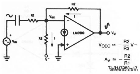
This circuit uses one section of an LM3900 to form an ac amplifier with a negative power supply. The dc biasing current, I, is established by the negative supply voltage through R3, and provides a very stable output-quiescent point for the amplifier. National Semiconductor, Linear Applications Handbook 1991 p 221 (View)
View full Circuit Diagram | Comments | Reading(602)
CHOPPER_TYPE_REGULATOR
Published:2009/7/10 22:24:00 Author:May

To oblain 10V at 1 amp from satellite solar cell supply with 97% effidency, differential amplifier in comparator stage produces error voltage to con trol Schmitt trigger, driver, and pctss switch.This achieves regulation by chopping current flow into filler for discrele intervals.-C. An-dren, High-Efficiency Voltage Regulator, Electronics, 37;23, p64-5. (View)
View full Circuit Diagram | Comments | Reading(932)
TIME_MARK_GENERATOR
Published:2009/7/10 22:22:00 Author:May

Produces precisely spaced output pulses suitable for calibrating CRO time bases. Can be programmed in binary by using 2240 for A, or in BCD by using 2250.Use crystal oscillator or other high-accuracy source for external clock, Time interval of output pulse is equal to clock width multiplied by n + 1, where n is number programmed into A, (1 to 255 for 2240 and 1 to 99 for 2250). Circuit can be programmed electronically by microprocessor if desired.-W. G. Jung, IC Timer Cookbook, Howard W. Sams, Indianapolis, IN, 1977, p218-220. (View)
View full Circuit Diagram | Comments | Reading(1275)
RADAR_TRANSPONDER
Published:2009/7/17 4:13:00 Author:Jessie

Used in missiles for tracking during test firing on range. Semi-conductor modulator minimizes power drain and thereby reduces heating in transponder, while providing r-f output pulse having extremely fast rise and fall times. Delay stability gives range accuracy of 1 yard.-L. Diven, Solid-Stage Modulator Feeds Subminature. Transponder, Electronics, 33:27, p 48-51. (View)
View full Circuit Diagram | Comments | Reading(1355)
| Pages:798/2234 At 20781782783784785786787788789790791792793794795796797798799800Under 20 |
Circuit Categories
power supply circuit
Amplifier Circuit
Basic Circuit
LED and Light Circuit
Sensor Circuit
Signal Processing
Electrical Equipment Circuit
Control Circuit
Remote Control Circuit
A/D-D/A Converter Circuit
Audio Circuit
Measuring and Test Circuit
Communication Circuit
Computer-Related Circuit
555 Circuit
Automotive Circuit
Repairing Circuit