
Circuit Diagram
Index 789
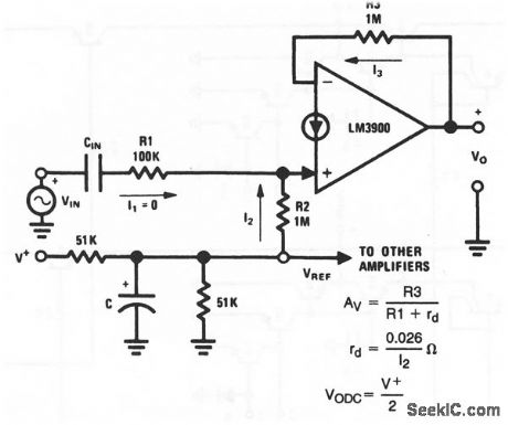
Norton_inverting_ac_amplifier_with_NVSUBBE_SUB_biasing
Published:2009/7/17 4:11:00 Author:Jessie

This circuit shows both an inverting ac amplifier and a third method for biasing. The input bias voltage VBE establishes a current through R3 to ground, This current comes from the amplifier output, so VO must rise to a level that causes the current to flow through R2. VO is calculated from the ratio of R2 and R3, as shown by the equations. When this NVBE biasing is used, R1 and R2 are established first, then R3 is added for the desired VO. National Semiconductor Linear Applications Handbook 1991 P220 (View)
View full Circuit Diagram | Comments | Reading(613)
ACTIVE_TONE_CONTROL
Published:2009/7/11 1:13:00 Author:May

The use of a low noise LM387 in a feedback circuit provides 20-dB boost or rejection of treble and bass. The supply voltage is +24 V. (View)
View full Circuit Diagram | Comments | Reading(1839)
ROBOTIC_MOTOR_CONTROL_CIRCUIT
Published:2009/7/17 4:11:00 Author:Jessie

This circuit, with three light sensors and three relays, was used to allow a robot to follow a light beam. Loss of the beam causes relay actuation, which controls a motor that produces corrective action. (View)
View full Circuit Diagram | Comments | Reading(660)
BAXANDALL_TONE_CONTROL_AUDIO_AMPLIFIER
Published:2009/7/11 1:12:00 Author:May
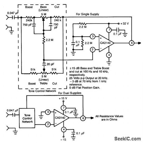
This circuit exploits the high slew rate, high input impedance, and high output-voltage capability of CA3140 BiMOS op amp. It also provides mid-band unity gain with standard linear potentiometers. (View)
View full Circuit Diagram | Comments | Reading(809)
SIMPLE_REMOTE_CONTROL_INTERFACE_CIRCUITS
Published:2009/7/17 4:11:00 Author:Jessie

If you want to control a dc motor, a momentary load, or an on/off load, these are some useful interface circuits. Figure A shows a dc-motor controller that requires the outputs of two different channels (CH1 and CH2). Note that it doesn't matter if the channel outputs are active low or high; what matters is that CH1 must be different from CH2 for the motor to be energized. The circuits in Figs. B and C are momentary-load controllers for active high and active low channel outputs, respectively. The circuit in Fig. D is a toggled-load controller. If you have an active high channel out-put, you must add the inverter shown. (View)
View full Circuit Diagram | Comments | Reading(882)
Free_running_multivibrator_using_an_ECG955M_timer_oscillator_chip
Published:2009/7/17 4:10:00 Author:Jessie

Free-running multivibrator using an ECG955M timer/oscillator chip. The external capacitor charges through RA and RB, but discharges through RB only. The photo shows the actual waveforms generated. The free-running frequency can be easily found by referring to the graph (courtesy GTE Sylvania Incorporated).
(View)
View full Circuit Diagram | Comments | Reading(586)
TIME_OUT_CIRCUIT
Published:2009/7/11 1:11:00 Author:May

This circuit operatesin the astable mode and at the end of the first period (up to several minutes), itproduces a tone,When S1is placed h the time position,Q3 is cut off because pin 3 of U1 is high and D1 holds Q3in cutoff.Q2is off,and Q1is on,which grounds the negative end of D2 and C2,Therefore,C1and C2 are returned to ground.After a time of about 1.1 R6(C1 + C2),the timer cycle completes and pin 3 U1 goeslow,This turns on Q3 and Q2,cuts off Q1,and effectively disconnects C2.Now,the circuit oscillates with a period determined by,R7 and C1,because D2is forwardˉbiased. A toneis then generated and can be heard from SPKR1.Closing S2 resets the circuit. (View)
View full Circuit Diagram | Comments | Reading(656)
IMPROVED_ONE_SHOT
Published:2009/7/17 4:10:00 Author:Jessie

Improvement of basic circuit uses less power and fewer components, while providing higher timing accuracy.-T. G.. Ellestad, Improved One-Shot Output Circuits, EEE, 13:8, p 67. (View)
View full Circuit Diagram | Comments | Reading(585)
LONG_DURATION_TIME_DELAY
Published:2009/7/11 1:07:00 Author:May

Transistor Q1 and resistors RI, R2, and R3 form a constant current source and the charge cur-rent might be adjusted to be as low as a few nanoamperes. This current would, of course, not be sufficient to fire the UJT where Ip=0.2 μA, unless the peak current was supplied from another source. Field-effect transistor Q2, acting as a source follower, supplies the current flowing into the emitter lead prior to firing and diode D1 provides a low-impedance discharge path for CE. D1 must be selected to have a leakage that is much lower than the charge current.Because IB is small, the delay time will vary linearly with R3. The voltage (E), applied across R3 and the base-emitter junction of Q1, is set by the variable resistor R1. Time delays up to 10 hours are possible with this circuit. Resistor R4, in series with the FET drain terminal, must be large enough not to allow currents in excess of IV to flow when the UJT is on. Otherwise, the UJT will not turn off and the circuit will latch up. (View)
View full Circuit Diagram | Comments | Reading(2182)
AUTOMATIC_WATERING_SYSTEM_CONTROLLER
Published:2009/7/17 4:10:00 Author:Jessie

Two probes are inserted into the soil. When the soil is wet, it is more conductive and Q1 is for-ward-biased, cutting Q2 off. As the soil dries, Q1 loges bias, allowing Q2 to turn on, actuating the relay RY1. RY1 closes, operating the watering-system control valve. When the soil is sufficiently moist, Q1 turns on, cutting off Q2, RY1, and the water valve. (View)
View full Circuit Diagram | Comments | Reading(1015)
SIMPLE_REMOTE_CONTROL
Published:2009/7/17 4:10:00 Author:Jessie

Here is a remote-control transmitter and receiver. The theory of the circuit's operation is very simple. The transmitter (Fig. A) generates IR light pulses at a frequency of 320-Hz (set in part by R2). The pulses arrive at the collector of the phototransistor and are amplified by the 2N2222 transistor. An NE567, IC2, is tuned to 320-Hz (by R6), so if pulses of any other frequency arrive at the phototransistor, the NE567's output will remain high. When the 320 Hz signal enters the phototransistor, the NE567 recognizes this frequency and pulls its output low. If you wish to change the NE567's operating frequency, you will have to adjust R2 and R6 to the same value. Keep in mind that the NE567 will work between 100 Hz and 1 kHz. You can also add more resistors (for more frequencies) instead of R2, and more NE567s tuned at the desired frequencies in order to make a multichannel remote control system. (View)
View full Circuit Diagram | Comments | Reading(6825)
ADJUSTABLE_TIMER
Published:2009/7/11 1:05:00 Author:May


LEDs indicate at a glance what the status of the circuit is al any given moment. Once the reset switch, S1, makes contact, the timer remains in that state until the start switch, S2, is pressed. When either switch is activated, LED1 (ready) and the time indicator, LED2, keep track of the situation. Although not necessary, the two LEDs should be of different colors (for example, red for ready and green for time ). (View)
View full Circuit Diagram | Comments | Reading(748)
Norton_noninverting_ac_amplifier_with_voltage_reference_biasing
Published:2009/7/17 4:10:00 Author:Jessie
This circuit shows both a noninverting ac amplifier and a second method for dc biasing. As in the case of the Fig. 11-32 circuit, the ac gain of this circuit is set by the ratio of the feedback resistor to the input resistor. However, the small-signal impedance of the internal diode at the (+) input must be added to the values of R1 when calculating gain, as shown by the equations. National Semiconductor Linear Applications Handbook, 1991, p 220, (View)
View full Circuit Diagram | Comments | Reading(593)
10_MINUTE_ID_TIMER
Published:2009/7/11 1:00:00 Author:May


Designed to automatically identify a transmitter every 10 minutes, this 555 circuit has adjustable charge and discharge paths. The IC should be a standard 555 type, not a CMOS type. C3 should be tanta-lum. The relay is a small 5-V reed type. (View)
View full Circuit Diagram | Comments | Reading(1155)
One_shot_multivibrator_using_an_ECG955M_timer_oscillator_chip
Published:2009/7/17 4:09:00 Author:Jessie

One-shot multivibrator using an ECG955M timer/oscillator chip. Upon application of a negative trigger to pin 2 the flip-flop is set, which releases the short circuit across the external capacitor. This dives the output high. The photo shows the actual waveforms generated in this mode. The time that the output is high is given by t= 1.1 RA C and can be easily determined by the graph showing time delay. Applying a negative pulse to reset terminal 4 cluing the timing cycle discharges the capacitor and causes the cycle to start again. When the reset function is not used it is recommended that it be connected to supply voltage to avoid false triggering (courtesy GTE Sylvania Incorporated). (View)
View full Circuit Diagram | Comments | Reading(780)
RADAR_POWER_AMPLIFIER
Published:2009/7/17 4:09:00 Author:Jessie
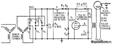
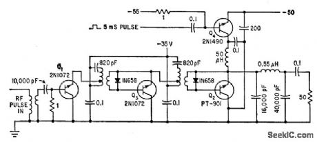
Handles pulses in range of 100 to 500 microsec at 2.2 Mc. Class B final stage Q2 delivers 105 w to piloading network serving as 5l-ohm load.-S. Horowitz and L. Humphrey, Satellite Sounder and Telemeter Chart Ionosphere Electron Density, Electronics, 34:25, p 50-53. (View)
View full Circuit Diagram | Comments | Reading(843)
WATCHDOG_TIMER_ALARM
Published:2009/7/11 0:59:00 Author:May


The watchdog timer contains a counter, IC3, in addition to the usual retriggerable 555 timer, IC1. The counter will sound an audible alarm if the watchdog timer trys to reset the μP a certain number of times (8, in the case of the counter). The alarm indicates that despite numerous resets, the system μP has failed to restart successfully, and the system is truly dead.A second 555 timer, IC2, resets the counter, 1C3, for the duration of the manual system restart. The design could be modified so that system μP resets the counter. (View)
View full Circuit Diagram | Comments | Reading(1525)
MULTIVIBRATOR_CONTROLLED__RELAY
Published:2009/7/17 4:09:00 Author:Jessie

Control signal is used to trigger mvbr that operates relay when input signal is greater than predetermined level (about 10 mv), and releases relay immediately when signal falls below this level.-G. B. Miller, Multivibrator Operates Relay, Electronics, 31:49, p 106-112. (View)
View full Circuit Diagram | Comments | Reading(547)
SCR_TIMER
Published:2009/7/11 0:58:00 Author:May

Depending on the R1 (adjustable) C1 time con-stant, when C1 charges up to a certain level, Q1 conducts, triggers SCR1, and sounds BZ1. A push-button resets the circuit. (View)
View full Circuit Diagram | Comments | Reading(646)
SPRINKLER_GUARDIAN_
Published:2009/7/17 4:09:00 Author:Jessie

The Sprinkler Guardian can be used in conjunction with any sprinkler controller that uses standard 24-Vac valves. The add-on unit senses the moisture content at the ground surface; if the ground is dry, the unit allows the controller to execute all the ON times preset by the controller clock. The unit obtains its power supply from the controller that it is used with. The output of U1 supplies a regulated 12 V to the rest of the circuit. The ground probes are connected to terminals 1 and 2 of TB2. Resistor R2 is used to balance the resistance of the earth between the two probes so that op amp U2, which is configured as a comparator, outputs a high when the ground is dry. PNP transistor Q1 is turned off, K1 is not energized, and terminals 1 and 2 of TB3 are shorted. Under those con-ditions, if the controller calls for watering the lawn, watering will commence. Now, assume that the ground is wet. The resistance between the probes drops, causing the output of U2 to go low, which turns on Q1. That energizes K1. Under those conditions, even when the controller is programmed to water, the valves will not open. Now assume that the soil is dry. Relay K1 is off. When the programmed watering time arrives, the water valve is opened, starting the timed watering cycle. The probes are wetted immediately, and U2 goes low. As the voltage output of U2 drops, a negative-going pulse is delivered through C4 to pin 2 of U3, a 555 timer, which triggers the timer into operation. The time output from pin 3 turns Q2 off, which keeps K1 from closing during the time cycle deter-mined by R8 and C7. That allows time for the sprinkler system to complete the watering cycle. A DPDT switch, S1, is used to place the circuit in either the automatic or manual mode. In the automatic mode, the circuit operates as previously described. In the manual mode, the terminals of TB3 are shorted, effectively removing the Guardian from the system. (View)
View full Circuit Diagram | Comments | Reading(1150)
| Pages:789/2234 At 20781782783784785786787788789790791792793794795796797798799800Under 20 |
Circuit Categories
power supply circuit
Amplifier Circuit
Basic Circuit
LED and Light Circuit
Sensor Circuit
Signal Processing
Electrical Equipment Circuit
Control Circuit
Remote Control Circuit
A/D-D/A Converter Circuit
Audio Circuit
Measuring and Test Circuit
Communication Circuit
Computer-Related Circuit
555 Circuit
Automotive Circuit
Repairing Circuit