
Circuit Diagram
Index 797
SAUARE_WAVE_CLOCK
Published:2009/7/10 22:51:00 Author:May

One section of Harris HA-4900/4905 precision quad comparator gives excellent frequency stability as self-starting fixed-frequency square-wave generator for clock applications, R1 and C1 determine frequency, and R2 provides regenerative feedback.For higher precision at frequencies up to 100 kHz, crystal may be used in place of C1.- Linear & Data Acquisition Products, Harris Semiconductor, Melbourne, FL, Vol. 1, 1977, p 2-96. (View)
View full Circuit Diagram | Comments | Reading(539)
ANSWERING_MACHINE_BEEPER
Published:2009/7/10 22:51:00 Author:May

When the light on the answering machine blinks, the resistance of photoresistor R1 charges, triggers the timer (U1), and generates 0.2-s pulse that activates BZ1. R1 is optically coupled to the LED on the answering machine and is properly light shielded. (View)
View full Circuit Diagram | Comments | Reading(594)
TWO_PHASE_CLOCK_TO_1_MHz
Published:2009/7/10 22:51:00 Author:May

Signetics 555 timer is used as oscillator to generate nonover-lapping clock pulses as required for most two-phase dynamic MOS memories and shift registers. Duty cycle is determined by values of extemal resistors RA and RB which, together with timing capacitor C, determine frequency of os cillation. 7473 flip-flop controls phase that is switched on through 7402 NOR gates. Article gives timing waveforms and equations. Maximum operating frequency is 1 MHz.-G. Schlitt, Monolithic Timer Generates 2-Phase Clock Pulses, EDNMagazine, Aug. 1, 1972, p 57. (View)
View full Circuit Diagram | Comments | Reading(783)
FAHRENHEIT_CENTIG_RADE_LED_THERMOMETER
Published:2009/7/10 22:50:00 Author:May


National LX5700 temperature transducer provides input for code conversion circuit driving 3-digit LED display indicating temperature range from -40℃ to +100℃ or -40°F to +199°F under control of ganged switch.- Linear Applications、,Vol. 2, National Semiconductor,Santa Clara.CA.1976,LB-30. (View)
View full Circuit Diagram | Comments | Reading(1043)
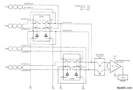
THERMOCOUPLE_MULTIPLEXER
Published:2009/7/10 22:46:00 Author:May

Under control of logic input, DG509 four-channel differential analog multiplexer connects selected one of four thermocouples to instrumentation amplifier driving digital or other readout. To de- room temperature, but this arrangement will be couple sensors from instrumentation amplifier, sensitive to changes in a mbient temperature.-reference junction at 0'0 can be used as shown. Analog Switches and Their Applications, Sil-Altematively, bucking voltage can be set at iconix, Santa Clara, CA, 1976, p 7-77-7-78. (View)
View full Circuit Diagram | Comments | Reading(3307)
FOUR_PULSE_BURST
Published:2009/7/10 22:45:00 Author:May

Generates burst of four clock pulses each time switch is pressed, Modifications ean produce any desired number of pulses in burst. Reliability of pulse count is ensured by use of debouncing latch using pair of 7400 gates,VCC is +5V,-E.E.Hrivnak,House Cleaning the Logical Way,73 Magazine, Aug.1974,p 85-90. (View)
View full Circuit Diagram | Comments | Reading(680)
60_Hz_CLOCK_OUTPUT_FROM_555
Published:2009/7/10 22:45:00 Author:May
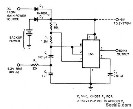
Basic 555 timer IC produces constant 60-Hz rectangular output for use as noninterruptible free-wheeling dock source. C1 introduces filtered 60-Hz power-line reference component across Ct at 2 V P-P. This signal overrides normal timing ramp of 555, causing it to act as amplifier or Schmitt trigger. When AC Iine power fails, Ct resumes normal function as timing capacitor for 60-Hz astable MVBR. Circuit can easily be adiusted for other reference frequencies.-W. G. Jung, Take a Fresh Look at New IC Timer Applications, EDN Magazine, March 20, 1977, p 127-135. (View)
View full Circuit Diagram | Comments | Reading(5830)
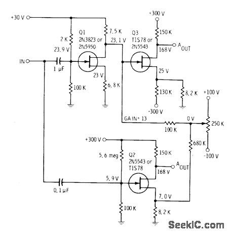
CHOPPER_STABILIZED_D_C_OPERATIONAL_AM_PLlFlER
Published:2009/7/10 22:44:00 Author:May

Mechanicctl chopper amplifier amplifies low-level d-c portion of input signal, for further amplilcation by stages that also am plify superimposed a-c information. Circuit has excellent d-c stability and wide band-width. D-c gain is l20 db and gain at 10 kc is 45 db.-Texas Inslruments Inc. Iron-sistor Circuit Design, McGraw-Hill, N.Y.1963,p195. (View)
View full Circuit Diagram | Comments | Reading(661)
TELL_A_BELL
Published:2009/7/10 22:44:00 Author:May

This accessory connects to phone and will activate an attention-getting 120-V bell whenever a ringing voltage appears on the phone line. The four-terminal transducer has a neon bulb close to a photocell, which are both enclosed in a light-tight tube. When the lamp is off, the cell is dark and its resistance is very high. When a ringing voltage appears on the phone line, the neon bulb glows brightly and illuminates the photocell whose resistance then drops to about 1000 Ω. The photocell is in the gate circuit of a triac that will turn on whenever the cell resistance drops. The triac is connected across the switching terminals of the isolation relay. Thus, the relay closes and applies 120 V to the output socket whenever the triac is on. (View)
View full Circuit Diagram | Comments | Reading(784)
PHOTOCONDUCTIVE_CHOPPER
Published:2009/7/10 22:42:00 Author:May

Combines low noise level With resistance to vibration.R1 prevemls bumup of photocell,R2 glves maximum conversion efficency at setting of about 2.2 meg.C1 averages d-c input signal fluctuations so they do not exceed 120-cps chopping frequency of light source.-R.G. Seed,Chopper Uses New Photocells,Electronics,31:21,p90-98. (View)
View full Circuit Diagram | Comments | Reading(483)
TELEPHONE_AUTO_RECORD
Published:2009/7/10 22:42:00 Author:May

The circuit requires neither a battery nor an ac supply to make it work. Set the recorder to the record position and when the telephone is taken off the hook, the recorder starts to record everything. When the phone is on the hook, the voltage across the phone lines is about 48 Vdc. When it is taken off the hook, the line voltage drops below 10 V. When the line voltage is near 48 V, the FET is biased off and no current can flow through Q2 and Q3. When the receiver is off the hook, the voltage drops, and allows Q1 to conduct. This action turns on Q2, Q3, and the cassette recorder. (View)
View full Circuit Diagram | Comments | Reading(680)
TRIGGERED_SWEEP_FOR_CRO
Published:2009/7/10 22:40:00 Author:May

Combination of 555 timer and standard opamp minimizes cost of adding triggered sweep to oscilloscope not having this feature. Timer is triggered by applying vertical-amplifier signal through opamp, initiating charging of sweep capacitor C. When capacitor voltage reaches control voltage of timer (0.33 VCC), flip-flop in timer resets and capacitor discharges to form retrace of sweep.- Signetics Analog Data Manual, Signetics, Sunnyvale, CA, 1977, p 726. (View)
View full Circuit Diagram | Comments | Reading(1636)
SIGNAL_SWITCHER
Published:2009/7/10 22:40:00 Author:May

Two-tube electronic switch serves in effect to provide simultaneous presentation of two different signals on CRO screen by switching signals alternately to vertical input at rate fast enough so both displays are seen.-Novice Q & A, 73 Magazine, March 1977, p 187. (View)
View full Circuit Diagram | Comments | Reading(594)
DIFFERENTIAL_TEMPERATURE_SENSOR
Published:2009/7/10 22:40:00 Author:May
Respands to difference in temperatures of MTS102 silicon high-precision temperature sensors having range of-40℃ to+150℃ With both sensors at same temperature,100K pot is adjusted so utputvo voltage is 0.000 V.Opamptypes are not crjtio al R1 is 27K for measurements in Celsius or kelvin and 15K for Fahrenheit measurements.- Silicon Temperature Sensors, Motorola,Phoenix,AZ,1978,DS 2536 (View)
View full Circuit Diagram | Comments | Reading(2364)
HIGH_Z_CRO_PREAMP
Published:2009/7/10 22:39:00 Author:May

Darlington circuit provides extremely high input impedance (over 2.2 megohms). With input shorted, noise level is 78 dB down as read at output whh VTVM. Linearity is within 1.5% for inputs from 100 μV to 1 mV, and frequency response is ±2 dB from 100 Hz to 350 kHz. Originally designed to boost input to CRO, but can be adapted to many other applications requiring high gain, low noise, and high input impedance.-J. Fisk, Circuits and Techniques, Ham Radio, June 1976, p 48-52. (View)
View full Circuit Diagram | Comments | Reading(687)
TEMPERAIURE_TO_FREOUENCY__CONVERTER
Published:2009/7/10 22:38:00 Author:May

Transistors Q1-Q5 in National LM3046 transistor array form oscillator and ramp that together convert varying output voltages of LX5600 temperature transducer to poportional changes in frequency of squatevwave pulses for feed to pulse counter.-P Lefferts, A New Interfacing Concept;the Monolithic TemperatureTransducer, National Semiconductor, Santa Clara,CA,1975,AN-132,p 4. (View)
View full Circuit Diagram | Comments | Reading(543)
TELEPHONE_INTERCOM
Published:2009/7/10 22:37:00 Author:May
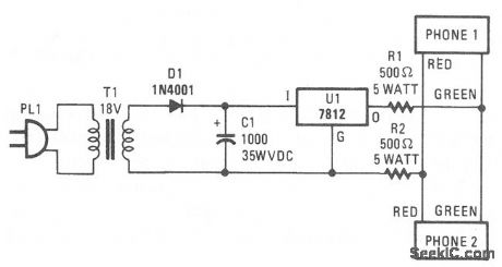
Two telephones can be used as an intercom setup with this simple power-supply arrangement. The 500-Ω resistors maintain line balance. (View)
View full Circuit Diagram | Comments | Reading(0)
CALCULATOR_KEYBOARD_INPUT
Published:2009/7/10 22:36:00 Author:May

Uses diode matrix that encodes 16 hexadecimal input keys as 4-bit code for microprocessor. Register holds conversion results. Multiplexer gives switch-selected 3-digit octal or 2-digit hexadecimal interpretation to inputs. Control logic serves for keyboard debouncing, cleafing, and entering data.Circuit eliminates need for entering programs with front-panel switches, by using keyboard to enter data in octal or hexadecimal form. Choice of form is achieved with 74157 multiplexors IC11 and IC12, set by S1. Article covers circuit operation in detail and gives 8008 full keyboard input program that defines memory address,with first 2 bytes, then enters loop that loads memory byte by byte in ascending address sequence. RGS-008A interface logic is used to control interface for RGS-008A computer.-J. Hoegerl, Calculator Keyboard Input for the Microcomputer, BYTE, Feb. 1977, p 104-107. (View)
View full Circuit Diagram | Comments | Reading(1987)
DIFFERENTIAL_VERTICAL_AMPLIFIER
Published:2009/7/10 22:36:00 Author:May
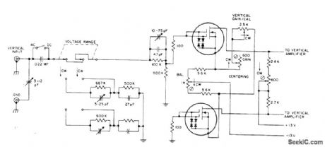
Uses two RCA 40841 dual-gate FETs invertical inputstage of solid-state oscilloscope,with gates of each connected in single-gate configuration.Circuit is designed for frequencies up to 500 MHz. Wide dynamic range permits handling of large signals、Mithout overloading.- Linear Integrated Circuits and MOS/FET's' RCA SolidState Division,Somerville,NJ,1977,p 435-436. (View)
View full Circuit Diagram | Comments | Reading(857)
ELECTROSTATIC_DEFLECTION_AMPLIFIER
Published:2009/7/10 22:35:00 Author:May
Circuit develops equal-amplitude but opposite-polarity sawtooth outputs when sawtooth input is applied to gates of Q1 and Q2. al is connected as common-source amplifier for applying opposite-polarity sawtooth to gate of Q3.Polarity at output of Q3 then becomes same as that of input, increased to amplitude suitable for deflction plates of CRT. Sawtooth at output of Q2 has opposite polarity. Circuit values are chosen to balance gain so both outputs have same magnitude.-E. M. Noll, FET Principles, Experiments, and Projects, Howard W. Sams, lndianapolis, IN, 2nd Ed., 1975, p 229-230. (View)
View full Circuit Diagram | Comments | Reading(886)
| Pages:797/2234 At 20781782783784785786787788789790791792793794795796797798799800Under 20 |
Circuit Categories
power supply circuit
Amplifier Circuit
Basic Circuit
LED and Light Circuit
Sensor Circuit
Signal Processing
Electrical Equipment Circuit
Control Circuit
Remote Control Circuit
A/D-D/A Converter Circuit
Audio Circuit
Measuring and Test Circuit
Communication Circuit
Computer-Related Circuit
555 Circuit
Automotive Circuit
Repairing Circuit