Amplifier Circuit
TELEPHONE_AMPLIFIER
Published:2009/6/22 22:57:00 Author:May | From:SeekIC

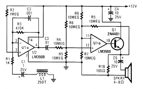
Section UI-a is configured as a high-gain inverting voltage amplifier that is inductively coupled to the phone line via L1. Inductor L1 is a homemade unit that consists of 250 turns of fine, enamel-coated wire that is wound on an iron core. The op amp receives the few mV produced by L1 via C1 and RI and amplifies the signal. Capacitor C1 acts as the negative-feedback component that limits the circuit's high-frequency gain, while R3 limits the low-frequency gain. Resistor R3 is particularly important because without it, the amplifier would saturate.Op amp UI-b is configured as a difference amplifier. It receives a signal from U1-a via C3 and R4 and amplifies the difference between it and half of the supply voltage. Transistor Q1 is configured as a common-collector amplifier ensuring sufficient signal to drive the speaker. Capacitor C5 is used to remove any dc component provided by transistor Q1.
Reprinted Url Of This Article:
http://www.seekic.com/circuit_diagram/Amplifier_Circuit/TELEPHONE_AMPLIFIER.html
Print this Page | Comments | Reading(3)

Article Categories
power supply circuit
Amplifier Circuit
Basic Circuit
LED and Light Circuit
Sensor Circuit
Signal Processing
Electrical Equipment Circuit
Control Circuit
Remote Control Circuit
A/D-D/A Converter Circuit
Audio Circuit
Measuring and Test Circuit
Communication Circuit
Computer-Related Circuit
555 Circuit
Automotive Circuit
Repairing Circuit
Code: