
Circuit Diagram
Index 572
PCD4421 Microcomputer Dialing Integrated Circuit
Published:2011/8/3 7:05:00 Author:Michel | Keyword: Microcomputer Dialing, Integrated Circuit
PCD4421 is the microcomputer dial-up integrated circuit produced by Dutch philips company and it is used in communication equipment and dial-up circuit.
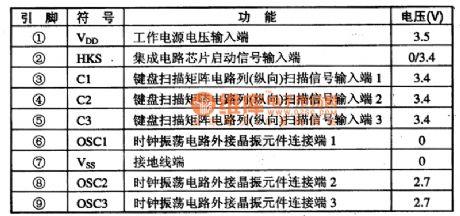
PCD4421 integrated circuit containins a number of frequent generating circuit, R key control circuit, the keyboard switch circuit and noise control decoding static circuit etc. This IC adopts feet 18 DIP package and the pins functions and data are shown as table 1.
Table 1:Pins Fuctions and Data ofPCD4421 IC (View)
View full Circuit Diagram | Comments | Reading(573)
Comparator Circuit of TL431
Published:2011/8/3 7:04:00 Author:Michel | Keyword: Comparator Circuit
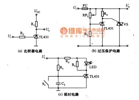
The picture a,b,c are comparator circuits of TL431.The picture (a) is comparator circuit of TL431.When input voltag9be Ui≥2.5V,the output voltage U。=2V;Ui<2.5V,the output U。=Ucc.
The picture (b) is protection voltage of TL431.When input voltage Ui exceeds 1+RRP1/R1)UREF, a larger current flows through the fuse,FU burns out to achieve the purpose of voltage protection.The picture (c) is delay circuit of TL431,the voltage on C1 is zero,TL431 stops and LED does not shine.With C1 charging voltage rises,TL431 conducts, LED displays by shining.The delay time(from input voltage to LED shining)is R1C1ln[Ui/(Ui-UREF)].S1 is reset switch, when it is connected,C1 discharges and prepares for the next delay. (View)
View full Circuit Diagram | Comments | Reading(3359)
Basic Voltage Regulating Circuit of TL431
Published:2011/8/3 6:45:00 Author:Michel | Keyword: Basic Voltage, Regulating Circuit

Picture a,b,c are basic voltage regulating circuit of TL431.TL431is composed of reference voltage and error amplifier.And it has the function of variable voltage regulating tube.It can be used as voltage regulating tube ,reference voltage and auxiliary circuit of power supply such as remote control ,overvoltage and multi-output circuits.It can also be used as simple control circuit current-limiting circuit of series regulator and its application is wide.Good voltage UREF temperature characteristic,fast connection and cuttoff,1~100mA absorbing current,low output noise and low output resistance are features of the device.
The picture (a) is simple parallel regulator circuit of TL431 and the output voltage U。=[(1+RRP1/R2)]UREF.In the formula,UREF is the reference voltage of TL431. (View)
View full Circuit Diagram | Comments | Reading(3380)
Power Supply Circuit of LTC1422
Published:2011/8/3 7:02:00 Author:Michel | Keyword: Power Supply Circuit

The power supply circuit of LTC1422 is as above.When the input voltage is connected,regulated diode VD1 controls the voltage of LTC1422 Vcc(8 feet) and Gnd(feet 4) and the voltage is 10V.GATE(feet 6)begins to output low PWL and it is connected to MOSFET(VT3) source.the gate of VT3 is connected to voltage Ui and the potential is higher than source,thus it can not be stopped.When the voltage on FB(feet 5) is lower than 1.232V.SET(comparator output end) pin turns into low PWL,VT2 and VT4 conducts,which makes the VT1 gate reach the ground.
For the minum timing cycle,ON pin becomes high PWL once and the charging pump begins to work and voltage on GATE pin rises in 1OμV/S slope.When the voltage on GATE pin rises to 1.232V,the voltage on FB pin rises, which makes the voltage on RESET pin rise and VT2 and VT4 conduct. (View)
View full Circuit Diagram | Comments | Reading(775)
Micropower Backup Power Supply Circuit of Voltage on Telephone Line
Published:2011/8/3 7:01:00 Author:Michel | Keyword: Telephone Line, Micropower, Backup, Power Supply Circuit

The micropower backup power supply circuit of voltage on telephone is as above.The input voltage Ui of micropower backup power supply absorbs from 24~28V telephone line and the input current is lower than 4μA.The output voltage U。of micropower backup power supply is 3.3V and the current is 1μA.In the circuit,VT1 and VT2 are current source and they provide about 3μA current for A1.A1 are reference voltage circuit and comparator circuit and the maximum static current consumption current is 0.6μA. (View)
View full Circuit Diagram | Comments | Reading(850)
SDA6000 System Control Microcomputer Integrated Circuit
Published:2011/8/3 7:30:00 Author:Michel | Keyword: Microcomputer, Integrated Circuit


SDA6000 is a new type system control microcomputer integrated circuit that is widely used in EURO7 and GIGAP5O0 series big screen color TV of Panasonic.
First,Functions and Features
SDA6000 integrated circuit has two pieces of the usual memory chips, one is 8M rapid FLASH memory (a FLASH) solid ROMR read memory and it is used in system of data read.The other one is the 16M SDRAM conventional memory (RAM). This configuration storage capacity is much larger than the average color TV set, and can fully satisfy completing new function needs of the multi-function large screen color TV.
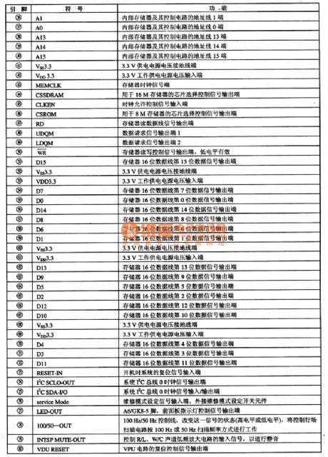
Second,Pins FunctionsSDA6000 integrated circuit uses 128 feet square structure and its pins functions are shown as table 1.
Table 1:SDA6000 IC Pins Functions and Data (View)
View full Circuit Diagram | Comments | Reading(676)
S2560 Microcomputer Dailing Integrated Circuit
Published:2011/8/3 7:16:00 Author:Michel | Keyword: Microcomputer Dailing, Integrated Circuit
S2560 is the microcomputer dialing integrated circuit produced by American Microsoft Company and it is used in communication equipment and dialing integrated circuit.
S2560 integrated circuit can transfer keyboard input transformation into pulse signal output.It can also have storage telecommunication and suspending and redialing functions.It uses feet 18 DIP package structure and its pins functions and data are shown as table 1.
Table 1:S2560 IC Pins Functions and Data (View)
View full Circuit Diagram | Comments | Reading(584)
4-20 mA Input and 5 V Output I/V Switching Circuit of LM324
Published:2011/8/1 22:23:00 Author:Michel | Keyword: 4-20 mA Input, 5 V Output, I/V Switching Circuit

The simple way to solve the above problem is that the buffer processing circuit composed of operational amplifier is installed before singal chip inputs and it is showed as the picture.Increasing this level operation amplifier can make zero processing become easier and it will not cost SCM internal resources.Especially,when single chips uses A/D interface to receive the input of voltage whose zero signal is not zero,which ensures A/D conversion digits capital can be all used in the useful signal.
Take 4 ~ 20 mA for example, the RA0 of picture B is current sampling resistor, and its value is restricted by the sensor power supply voltage, when the current level uses 24 V power supply, RA0 often uses 500 Ω resistance when it is 24V power supply. The voltage is changed into 10V when it's 20mA. (View)
View full Circuit Diagram | Comments | Reading(8816)
OP07 4-20mA Input or 5V Output I/V Converting Circuit
Published:2011/8/1 22:31:00 Author:Michel | Keyword: OP07, 4-20mA Input, 5V Output , I/V Converting Circuit

The circuit is a good recommended line circuit.First of all,it uses high precision voltage regulation circuit composed of TL431 with DIP encapsulation .The dissipation power reaches 1W because TL431 uses DIP encapsulation and it's easy to change dividing resistor by altering power supply voltage.Second,operational amplifiers choose the high precision and low disorders, OP07 and its parameter index is much better than common cheap op-amp.The key is that the output voltage of the op-amp ICC is equal to zero when the input is four mA on zero signal processing.
Work Principle of this Part CircuitThe same phase input port voltage of Op-amp ICD is porvided by negative power which regulated by TIA31 and it divides voltage via R15 and R14. (View)
View full Circuit Diagram | Comments | Reading(4031)
Inductance Three-point LC Oscillator Circuit
Published:2011/8/1 22:24:00 Author:Michel | Keyword: LC Oscillator Circuit


The picture 1 is inductance three-point LC oscillator circuit.Inductance coil L1 and L2 is a coil and 2 point is middle tap.If we suppose that the collector current decreases at a moment and the coil's instantaneous polarity is shown as the picture 1.The triode in the left usescommon-base configuration thus it makes net input of emitter junction decrease and collector current decrease,which is accordwith positive feedback's phase condition.The picture 2is another kind of inductance Bikini LC oscillator circuit.
Pic ture 1:InductanceThree-point Oscillator(CB)
Picture 2:Inductance Three-point LC Oscillator(CE) (View)
View full Circuit Diagram | Comments | Reading(1385)
Infrared Control Telephone Code Lock Circuit
Published:2011/8/1 0:31:00 Author:Michel | Keyword: Infrared Control, Telephone Code Lock
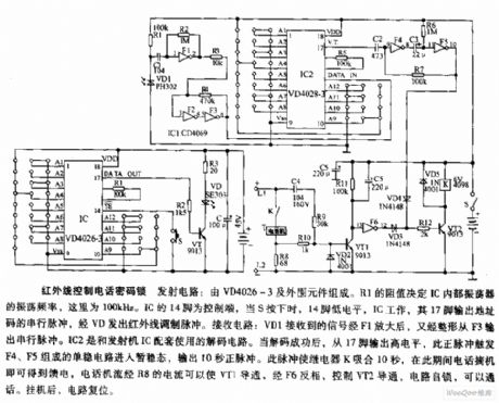
The infrared control telephone code lock emitting circuit is composed of VD4026-3 and peripheral components. R1 resistance value decides the IC internal oscillator oscillation frequency, here it's 100 KHz.IC 14 feet is control circuit.14 feet outputs low PWL and 17 feet outputs address serial pulse and launches infared adjusting pulse when S is pressed.Receiving circuit:VD1 receiving signal is amplifiedvia F1 and it's surged and then it outputs serial pulse via F3.IC2 is decoding circuit of transmitter IC.When the decoding is finished successfully,high PWL is output from 17 feet,the positive pulse makes F4 and F5 monostable circuit enter transition state and it outputs 10s positive pulsr and the pulse make relay K actuate 10 S.
(View)
View full Circuit Diagram | Comments | Reading(660)
Low Noise 200MHZ Broadband Amplifier Circuit
Published:2011/8/1 5:38:00 Author:Sue | Keyword: Low Noise, Broadband, Amplifier

The circuit consists of two CX35D. The main technological indicators are: bandwidth of 10-20MHz; When the load resistance value is 500Ω, the voltage gain Au is not less than 80; the undistorted output voltage is not less than 500mV; the short noise which is put on input terminal is less than 40μV. When the capacitors which are connected to pin5,pin9,pin10 are adjusted, the band width can reach 300KHz; Every level should be shielded;Transistor's characteristic frequency should be larger than 1000MHz. (View)
View full Circuit Diagram | Comments | Reading(941)
motor flashing lights controller(4)
Published:2011/7/25 2:08:00 Author:chopper | Keyword: motor, flashing lights, controller

This example describes the motor flashing lights controller with three functions like lights cycle,braking flash,and steering flash,and it can be taken as the taillights' decorative lights of motorcycles or cars. The principle of circuit The motor flashing lights controller circuit includes low-frequency oscillator,brake/nocturnal light control circuit, turn light control circuit and LED circuit, just as 7-28 shows.
The low-frequency oscillator circuit consists of D1 within the Schmitt trigger integrated circuit IC (D1-D6) , resistors R1, R2, capacitor C1 and diodes VD7, VD8. Brake / nocturnal light control circuit is formed by the resistors R3-R8, capacitor C2, C3 diodes VD1, VD2, VD5, VD6, VD9-VD11, VD23 and crystals V1, V2.
(View)
View full Circuit Diagram | Comments | Reading(912)
motor headlamp auto-changing controller(4)
Published:2011/7/25 2:10:00 Author:chopper | Keyword: motor, headlamp, auto-changing controller

This example describes motor headlamp auto-changing controller produced by CD4011 digital integrated circuit,it can automatically transform the high beam and low beam of motor when the motors meet(turn the high beam into low beam),and it will resume after meeting.The principle of circuitThis motor headlamp auto-changing controller includes power supply circuit, optical control circuit,and control executive circuit,which is shown as picture7-4.
Power supply circuit is formed by the current limiting resistor R4, three-terminal voltage regulator integrated circuit IC2 and filter capacitor C. Light control circuit consists of resistor R1, photosensitive resistor RG and four nand-gate integrated circuits IC1 (D1-D4).
(View)
View full Circuit Diagram | Comments | Reading(618)
planter fertilization tube blockage alarm
Published:2011/7/25 1:04:00 Author:chopper | Keyword: planter, fertilization tube, blockage alarm

This example describes the planter fertilization tube blockage alarm,which can send the sound and light alarm signal to alert the staff to process timely when the fertilizertube is jammed. The principle of circuit The planter fertilization tube blockage alarm circuit is formed by the transistors V1-V5,the potentiometers RP1-RP4,relay K, indicator light HL,buzzer HA,power switch S and battery GB,which is shown in figure 4-106.
(View)
View full Circuit Diagram | Comments | Reading(650)
DC power supply screen,DC cabinet
Published:2011/8/1 3:27:00 Author:chopper | Keyword: DC power supply screen, DC cabinet

Field of application:GZDW series DC power supply cabinet is suitable for 10 ~ 500kV transformer substations, power plants and high-rise buildings, residential quarters and other power distribution rooms, and the small captive power plant, as high pressure switch, relay protection,and the automatic devices ,control power supply and emergency lighting power. Also it can be applied to other places needing DC power supply.
(View)
View full Circuit Diagram | Comments | Reading(838)
Explosion-proof electric motor soft starter
Published:2011/8/1 3:28:00 Author:chopper | Keyword: Explosion-proof, electric motor, soft starter

QJR1 mining explosion isolation and intrinsic safety motor soft starter(Soft starter for short) is a high-tech product produced by our company. It adopts advanced microprocessors, on-line control and power electronic control technology to achieve a soft start of motor to maximize the elimination of the mechanical and current shock and to extend the service life of equipments. It is the ideal replacement product for hydraulic coupling and other motor starting equipments, and it has advanced technology, safety, reliability, easy maintenance, long service life. (View)
View full Circuit Diagram | Comments | Reading(686)
Altima A33-EC car/space position PNP switch circuit
Published:2011/8/1 4:28:00 Author:Fiona | Keyword: car/space position, PNP switch

Altima A33-EC car/space position PNP switch circuit is shown as above:
ECM port and the measured reference value between every port and the ground Attention:when the circuit measures the input / output voltages,it can’t use the ECM ground port.It could lead to the damage of ECM transistor.It should use ECM port outside of the ground point (View)
View full Circuit Diagram | Comments | Reading(1065)
Altima A33-EC electronic control engine stents circuit
Published:2011/8/1 4:26:00 Author:Fiona | Keyword: electronic control engine
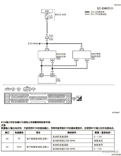
Altima A33-EC electronic control engine stents circuit is shown as above:
ECM port and the measured reference value between every port and the ground Attention:when the circuit measures the input / output voltages,it can’t use the ECM ground port.It could lead to the damage of ECM transistor. (View)
View full Circuit Diagram | Comments | Reading(936)
drive power circuit of LED energy saving lamp
Published:2011/7/27 8:32:00 Author:Fiona | Keyword: energy saving, drive power

LED power supply circuit mostly is composed of switching power supply circuit and feedback circuit,the feedback circuit takes sample from load place,then adjusts the pulse duty cycle or frequency for the switch circuit to achieve the purpose of controlling the switching circuit's output.
(View)
View full Circuit Diagram | Comments | Reading(5228)
| Pages:572/2234 At 20561562563564565566567568569570571572573574575576577578579580Under 20 |
Circuit Categories
power supply circuit
Amplifier Circuit
Basic Circuit
LED and Light Circuit
Sensor Circuit
Signal Processing
Electrical Equipment Circuit
Control Circuit
Remote Control Circuit
A/D-D/A Converter Circuit
Audio Circuit
Measuring and Test Circuit
Communication Circuit
Computer-Related Circuit
555 Circuit
Automotive Circuit
Repairing Circuit