
Circuit Diagram
Index 569
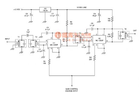
the absolutely useful switch power supply:the TDA two chips system power supply(A4)
Published:2011/8/13 6:49:00 Author:Ariel Wang | Keyword: absolutely useful , switch power supply, two chips system

View full Circuit Diagram | Comments | Reading(861)
the output circuit of any scale count using CD4017(2)
Published:2011/8/13 6:53:00 Author:Ariel Wang | Keyword: output, scale count
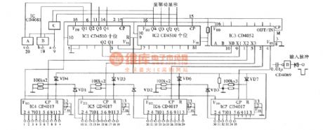
View full Circuit Diagram | Comments | Reading(836)
the demodulator circuit of the radio frequency :NE565 PLL FM detector
Published:2011/8/12 21:19:00 Author:Ariel Wang | Keyword: Demodulator, PLL, FM, detector, radio frequency
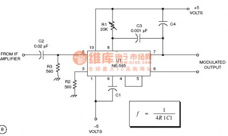
View full Circuit Diagram | Comments | Reading(3892)
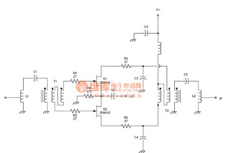
the IF circuit of the radio frequency:Filter switch RF circuit
Published:2011/8/12 21:21:00 Author:Ariel Wang | Keyword: IF, RF, Filter switch
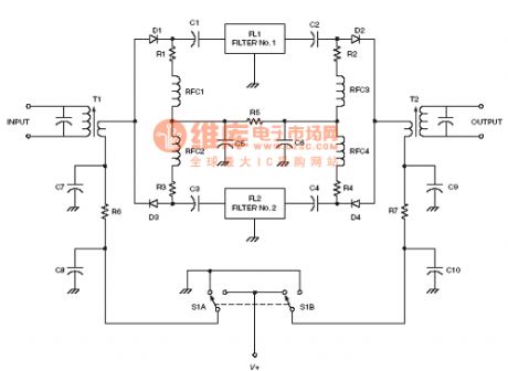
View full Circuit Diagram | Comments | Reading(1027)
the Oscillator circuit of the radio frequency :Buffered Butler oscillator RF circuit
Published:2011/8/12 22:05:00 Author:Ariel Wang | Keyword: Oscillator, radio frequency , Buffered, Butler

View full Circuit Diagram | Comments | Reading(1367)
the IF circuit of the radio frequency :NPN IF amplifier circuit
Published:2011/8/12 21:30:00 Author:Ariel Wang | Keyword: IF , radio frequency , NPN , amplifier
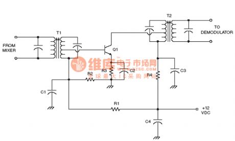
View full Circuit Diagram | Comments | Reading(666)
the IF circuit of the radio frequency :NPN IF amplifier circuit with AGC bias
Published:2011/8/12 21:32:00 Author:Ariel Wang | Keyword: IF, radio frequency , NPN , amplifier , AGC, bias
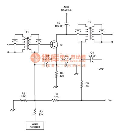
View full Circuit Diagram | Comments | Reading(922)
the IF circuit of the radio frequency :Universal IF amplifier circuit
Published:2011/8/12 21:33:00 Author:Ariel Wang | Keyword: IF, Universal, radio frequency , amplifier
View full Circuit Diagram | Comments | Reading(624)
the mixer circuit of the radio frequency :Dual NPN mixer RF circuit
Published:2011/8/12 21:36:00 Author:Ariel Wang | Keyword: Mixer, Dual, NPN , RF
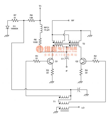
View full Circuit Diagram | Comments | Reading(857)
the mixer circuit of the radio frequency :Dual-gate MOSFET mixer RF circuit
Published:2011/8/12 21:35:00 Author:Ariel Wang | Keyword: Mixer, radio frequency , Dual-gate , MOSFET
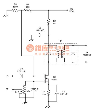
View full Circuit Diagram | Comments | Reading(2414)
the mixer circuit of the radio frequency :Dual JFET mixer RF circuit
Published:2011/8/12 21:40:00 Author:Ariel Wang | Keyword: Mixer, radio frequency , Dual , JFET
View full Circuit Diagram | Comments | Reading(1600)
the Mixer circuit of the radio frequency :Dual MOSFET mixer RF circuit
Published:2011/8/12 22:00:00 Author:Ariel Wang | Keyword: Mixer, Dual, MOSFET, RF
View full Circuit Diagram | Comments | Reading(613)
the mixer circuit of the radio frequency :JFET mixer RF circuit
Published:2011/8/12 22:01:00 Author:Ariel Wang | Keyword: mixer, RF, JFET

View full Circuit Diagram | Comments | Reading(2497)
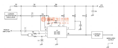
the demodulator circuit of the radio frequency :MC-1495 Product detector circuit
Published:2011/8/12 21:20:00 Author:Ariel Wang | Keyword: Demodulator, Product detector, radio frequency
View full Circuit Diagram | Comments | Reading(1450)
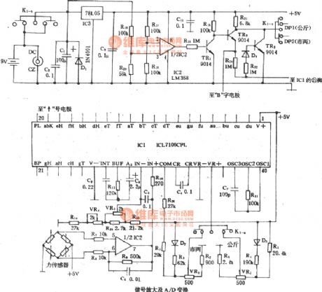
the automatic measuring instrument of DS-88C type
Published:2011/8/12 21:16:00 Author:Ariel Wang | Keyword: automatic, measuring instrument
View full Circuit Diagram | Comments | Reading(547)
the demodulator circuit of the radio frequency :FM discriminator circuit
Published:2011/8/12 21:13:00 Author:Ariel Wang | Keyword: demodulator, radio frequency , FM, discriminator
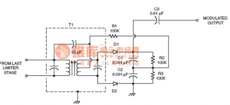
View full Circuit Diagram | Comments | Reading(1592)
the demodulator circuit of the radio frequency :CA3189E IF subsystem circuit
Published:2011/8/12 21:12:00 Author:Ariel Wang | Keyword: Demodulator, radio frequency, IF, subsystem
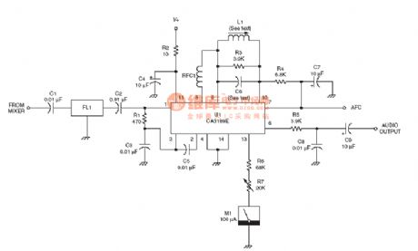
View full Circuit Diagram | Comments | Reading(1212)
the optical tester of 555
Published:2011/8/12 21:10:00 Author:Ariel Wang | Keyword: 555, optical tester
It is the optical tester circuit.It consists of photoelectric sensor,monoflop and audio circuit.The photoelectric sensor uses photocell 2CR33.
(View)
View full Circuit Diagram | Comments | Reading(849)
the amplier circuit of the radio frequency :Voltage-tuned Dual-gate MOSFET RF amplifier circuit
Published:2011/8/12 21:02:00 Author:Ariel Wang | Keyword: amplier, Voltage-tuned , Dual-gate, MOSFET, RF , amplifier
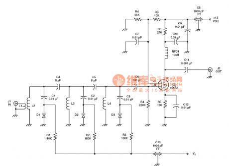
View full Circuit Diagram | Comments | Reading(2166)
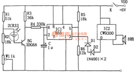
Monolithic Alarming Timer Circuit Diagram
Published:2011/8/9 17:57:00 Author:Vicky | Keyword: Monolithic, Alarming Timer

Monolithic Alarming Timer
IC1 is a 14 decimals counter/frequency divider and oscillator, which can work in a relatively wider range of frequency. When S1 closes, R4 and C2 can generate positive pulse when are turned on, and reset the counter. Then it begins counting. When it comes to 14 decimals, the 3 pin represents high level, and T1 drives the piezoelectric buzzer to produce sound. The time delay function can be adjusted by P1. Then relationship between time delay and parameters of components is shown as follows:
1 ~ 30 min: C1= 200mF; P1= 500KΩ;
1 ~ 60 min: C1= 470mF; P1= 500KΩ;
1 ~ 200 min: C1= 470mF; P1= 1MΩ. (View)
View full Circuit Diagram | Comments | Reading(815)
| Pages:569/2234 At 20561562563564565566567568569570571572573574575576577578579580Under 20 |
Circuit Categories
power supply circuit
Amplifier Circuit
Basic Circuit
LED and Light Circuit
Sensor Circuit
Signal Processing
Electrical Equipment Circuit
Control Circuit
Remote Control Circuit
A/D-D/A Converter Circuit
Audio Circuit
Measuring and Test Circuit
Communication Circuit
Computer-Related Circuit
555 Circuit
Automotive Circuit
Repairing Circuit