
Circuit Diagram
Index 575
The spectrum therapeutic apparatus
Published:2011/8/3 22:26:00 Author:qqtang | Keyword: therapeutic apparatus

Here is to introduce a spectrum therapeutic apparatus which can generate 600-700mm red spectrum. After being concentrated, the red light is shed on the ill part of the human body, which can assist to cure many diseases.(this is often called burning electricity , which adopts the photochemical effect to cure illness). The working principle of the circuit The spectrum therapeutic apparatus consists of the power supply circuit and oscillating output circuit, see as figure 9-27.
The power supply circuit consists of the fuse FU, power supply switch S, rectifier diode VD1-VD8, power supply transformer T1, filter capacitor C6, resistor R1 and R7, power supply indicating LED VL and fan motor M. (View)
View full Circuit Diagram | Comments | Reading(737)
The electric spark timer
Published:2011/8/3 22:29:00 Author:qqtang | Keyword: spark timer

The electric spark timer introduced in the illustration can not only test the gravity acceleration, but also be used to illustrate the breakdown conducting experiment of the air in the high pressure or the combustible gas lighting experiment. The working principleThe electric spark timer circuit consists of the power supply switch S, diode VDl-VD6, the regulated diode VS, thyristor VT, resistor Rl-R3, capacitor C, booster transformer T and discharging pole, see as figure 8-55.
When the power supply switch S is getting through and it is in the forward half-cycle, the current runs through VD1, R1, C and VD3, and becomes a circuit, C is starting to charge. (View)
View full Circuit Diagram | Comments | Reading(1369)
The car electric igniter (4)
Published:2011/8/3 22:33:00 Author:qqtang | Keyword: electric igniter
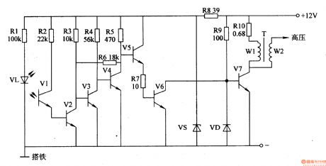
Here is to introduce the car electric igniter which adopts the photoelectric triggering method, and its feature is that neither of the trigger signal nor the closing angle is affected by the engine rotating speed.
The working principle of the circuit The car electric igniter circuit consists of the photoelectric trigger, amplifier circuit and switch booster circuit, see as figure 7-135.
The photoelectric trigger consists of the blanking disc (located between VL and VI, not in the figure), resistors of R1 and R2, infrared LED VL, infrared light sensitive transistor V1 and so on. The amplifier circuit consists of the transistor V2-V5, regulated diode VS and resistor R3-R6 and R8. (View)
View full Circuit Diagram | Comments | Reading(1042)
The ordinary pressure boiler temperature auto controller
Published:2011/8/3 22:36:00 Author:qqtang | Keyword: ordinary pressure boiler, controller

Here is to introduce the ordinary pressure boiler temperature auto controller which can automatically make the water pump work when the water in it reaches 85⁰C and stop working when the water is reduced to 50⁰C. The principle of the circuit The ordinary pressure boiler temperature auto controller consists of the power supply circuit, temperature detection control circuit, trigger, working state indicator circuit and control executing circuit, see as figure 8-154.
The temperature test controller circuit consists of the temperature sensor RT, resistor R1-R5, potentiometer RP1 and RP2, the op-amp integrated circuit IC (N1 and N2). (View)
View full Circuit Diagram | Comments | Reading(980)
The welder power regulator
Published:2011/8/3 22:55:00 Author:qqtang | Keyword: welder, power regulator

The welder power adjuster in the example can adjust the output voltage and current by changing the thyristor conducting angle, it can be used in the restructuring of common welders.
The working principle of the circuitThe welder power regulator circuit consists of the control switch S, thyristor VT, dual-way trigger diode VRP, resistor R1-R3 and capacitors of C1 and V2, see as figure 8-16.
Pull the control switch S to the position of 1 , the welder will be in the non-controlled state, the output power of the welder is under the control of the power regulator circuit, at the moment, the welder is working in full voltage and the output current is the maximum. (View)
View full Circuit Diagram | Comments | Reading(2896)
The industrial electric igniter
Published:2011/8/3 22:39:00 Author:qqtang | Keyword: electric igniter

The industrial electric igniter introduced here characterizes the high igniting energy and low producing cost, etc, it can be used in industrial oil oven, or used to light the oil in chemical and petroleum area, or used in starting ignition when the gas is burning.The principle of the circuit The industrial electric igniter circuit consists of the power supply circuit, starting ignition control circuit and booster ignition circuit, see as figure 8-149.
The power supply consists of the switch S1, fuse FU, step-down capacitor C1, releasing resistor R1, rectifier diode VD1, voltage stabilizing diode VS and filter capacitor C2. (View)
View full Circuit Diagram | Comments | Reading(1394)
The industrial magnetic eraser
Published:2011/8/3 22:43:00 Author:qqtang | Keyword: industrial magnetic eraser

Here is to introduced an industrial magnetic eraser whose working voltage is AC 220V, it characterizes simple structure, high power, strong field and so on. The working principle of the circuit The industrial magnetic eraser consists of the fuse FU, thyristor VT, dual-way trigger diode V, magnetic erasing coil L, resistor R, potentiometer RP, capacitor C, indicator HL and power supply switch S , see as figure 8-148.
When the power supply switch S is getting through, the AC 220V voltage is charging C through FU, HL, L, R and RP. When C is charged to the regulated value, V is broken down, which makes VT to be triggered and conducting, HL is glowing. (View)
View full Circuit Diagram | Comments | Reading(856)
The pressure tank gas pressure exception alarm
Published:2011/8/3 22:59:00 Author:qqtang | Keyword: pressure tank, gas pressure, exception alarm

The working principle of the circuit The pressure tank gas pressure exception alarm circuit consists of the pressure detection control circuit, LED indicating circuit and audio alarm circuit, see as figure 8-145.
The gas pressure detection control circuit consists of the power supply switch S, battery GB and the electric connector air meter Q.The LED indicating circuit consists of the green LED VL1, red LED VL2 and the resistors of R1 and R2.The audio alarm circuit consists of the audio integrated circuit IC, transistor V, resistor R3, capacitors of C1 and C2, diodes of VD1 and VD2, loudspeaker BL. (View)
View full Circuit Diagram | Comments | Reading(744)
The car electric igniter (1)
Published:2011/8/3 23:04:00 Author:qqtang | Keyword: electric igniter
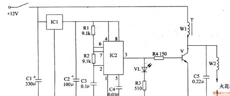
The principle of the circuit
The car electric igniter consists of the voltage stabilizing filter circuit, astable multi-resonance oscillator and booster circuit, see as figure 7-132.
The voltage stabilizing filter circuit consists of the filter capacitors of C1 and C2 and 3-terminal regulated circuit IC1. The astable multi-resonance oscillator consists of the resistors of R1 and R2, capacitors of C3 and C3, time-based integrated circuit IC2 and so on. The booster circuit consists of the LED VL, resistors R3 and R4, transistor V, booster transformer T and discharge capacitor C5. (View)
View full Circuit Diagram | Comments | Reading(688)
The winding engine auto limit controller
Published:2011/8/3 23:08:00 Author:qqtang | Keyword: winding engine, auto limit controller

Theworkingprincipleofthecircuit
The winding engine auto limit controller circuit consists of the knife switch Q, fuses of FU1 and FU2, heat relay KR, relay K, AC contactors of KM1 and KM2, rising control key S1, dropping control key S2, stop button S3, button self-lock control switch S4(S4-1S4-n), reed pipe SAl-SAn, power supply transformer T, rectifier diode VD and filter capacitor C, see as figure 8-142.
After the AC 220V voltage between the phase wire L1 and neutral line L is stepped down by T, rectified by VD and filtered by C, it provides with 12V DC voltage for the relay K. (View)
View full Circuit Diagram | Comments | Reading(785)
The heating magnetic mixer (1)
Published:2011/8/3 23:11:00 Author:qqtang | Keyword: magnetic mixer

Here is to introduce the heating magnetic mixer which has the functions of timely constant temperature heating and auto mix with magnetic power, it can be used in mining industrial manufacturing and scientific experiments. The working principle of the circuitThe heating magnetic mixer consists of the power supply circuit, heating control circuit, clock oscillating circuit, pulse distribution controller and electromagnetic controller, see as figure 8-138.
The power supply circuit consists of the power supply switch S1, power transformer T, rectifier bridge pile UR, 3-terminal regulated integrated circuit IC6, filter capacitors C3 and C4. (View)
View full Circuit Diagram | Comments | Reading(1075)
The car distance audio reminder (1)
Published:2011/8/3 23:15:00 Author:qqtang | Keyword: car distance, audio reminder
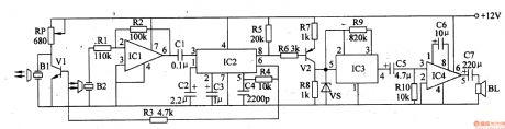
The working principle of the circuit The car distance language reminder circuit consists of the ultra-sonic emitter circuit, ultra-sonic receiver circuit, PLL circuit and audio reminding circuit, etc, see as figure 7-130.
The ultra-sonic emitter circuit consists of the ultra-sonic emitter B1, transistors of V1 and IC2, etc. The ultra-sonic receiver circuit consists of the ultra-sonic receiver B2, op-amp integrated circuit IC1 and external elements. The PLL circuit consists of IC2 and external elements. The audio indicating circuit consists of the transistor V2, language integrated circuit IC3, audio power amplifier integrated circuit IC4 and external elements. (View)
View full Circuit Diagram | Comments | Reading(575)
The automobile steering alarm (3)
Published:2011/7/29 4:35:00 Author:qqtang | Keyword: steering alarm
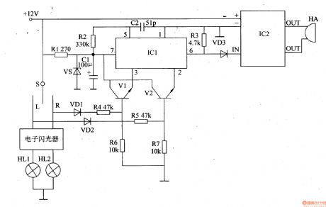
The working principle of the circuitThe automobile steering alarm consists of the regulated circuit, trigger circuit, audio circuit and audio output circuit, see as figure 7-126.
The regulated circuit consists resistor R1, regulated diode VS and filter capacitor C1. The trigger circuit consists of the diodes of VD1 and VD2, resistors R4-R7 and transistors of V1 and V2. The voice circuit consists of the voice integrated circuit IC1, resistor R2 and capacitor C2.The audio output circuit consists of the resistor R3, diode VD3, power amplifier circuit IC2 and ultra loud buzzer HA. (View)
View full Circuit Diagram | Comments | Reading(516)
The ultra-sonic safety alarm of car travelling
Published:2011/8/3 23:19:00 Author:qqtang | Keyword: ultra-sonic safety alarm, car travelling
The working principle of the circuitThe ultra-sonic safety alarm circuit of car travelling consists of the ultra-sonic wave detector, PLL audio decoder, trigger audio circuit and audio amplifier output circuit, see as figure 7-129.
The ultra-sonic wave detector consists of the the ultra-sonic wave emitter B1, ultra-sonic wave receiver B2, transistor V1, resistors of R1 and Rll-Rl9, potentiometer RP, capacitors C9-Cl2 and the op-amp integrated circuit lC4(Nl-N3). The PLL audio decoder consists of the audio decoder circuit IC1, resistor R2 and capacitors C1-C3. The trigger language integrated circuit consists of the resistors R3-R7, capacitor C4, transistor V2 and audio integrated circuit IC2. (View)
View full Circuit Diagram | Comments | Reading(421)
Cooking Timer Circuit
Published:2011/7/20 3:17:00 Author:Joyce | Keyword: Cooking , Timer
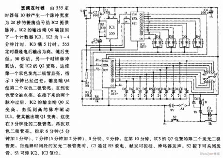
Cooking timer circuit is as shown in the figure:
Cooking Timer: Oscillating signal of 20 seconds pulsing width is produced by timer 555 every 10 seconds to provide pulse for IC2. The output end Q0 of IC2 is connected with the next timer IC3. The timing time of IC2 is 1~4 minutes and that of IC3 is 5 minutes. After the timer 555 is provided with power, its output is high, but becomes low afterwards. 30 seconds later, the arrival of another clock pulse will increase the value of Q2 of IC2, which indicates that 1 minute is gone by. The output end Q4 will lighten the first two-tone diode till the whole color tube is lightened. After the next two pulses, output end Q0 of IC2 becomes high again. The pulse changing from low to high will drive IC3 and increase its output end Q1. This will lighten the diode which is set at the point of 5 minutes. (View)
View full Circuit Diagram | Comments | Reading(1259)
Water Quality Detector Circuit
Published:2011/7/20 3:18:00 Author:Joyce | Keyword: Water Quality , Detector
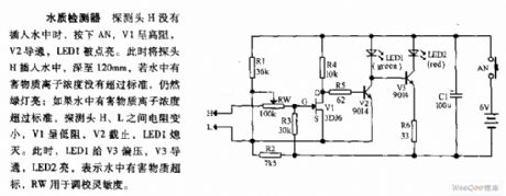
The water quality circuit is as shown in the figure:
Water Quality Detector Circuit: When the detecting head has not been inserted into the water, if one presses AN, V1 will display that the impedance is high, V2 will break over and LED1 will be lightened. Once inserting the detecting head into 120mm deep under the water, the green light will still be on if the concentration of ions of harmful substance has not exceeded the standard. If not so, the impedance between detecting head H and L will become smaller. Then V1 will show low impedance, V2 will cut off, and LED1 will go out. At this time, LED1 will offer bias voltage to V3 which will break over afterwards. And LED2 will be lightened, indicating harmful substance in the water has exceeded the standard. RW is used to adjust the sensitivity. (View)
View full Circuit Diagram | Comments | Reading(1592)
TIIDA-AV Audio Circuit Two
Published:2011/7/20 3:26:00 Author:Joyce | Keyword: TIIDA, AV, Audio

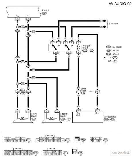
TIIDA-AV Audio Circuit (View)
View full Circuit Diagram | Comments | Reading(866)
TIIDA-AV Audio Circuit One
Published:2011/7/20 3:25:00 Author:Joyce | Keyword: AV, Audio
TIIDA-AV Audio Circuit (View)
View full Circuit Diagram | Comments | Reading(819)
TIIDA-BL Remote Door System Circuit Three
Published:2011/7/20 3:27:00 Author:Joyce | Keyword: TIIDA, BL, Remote Door System
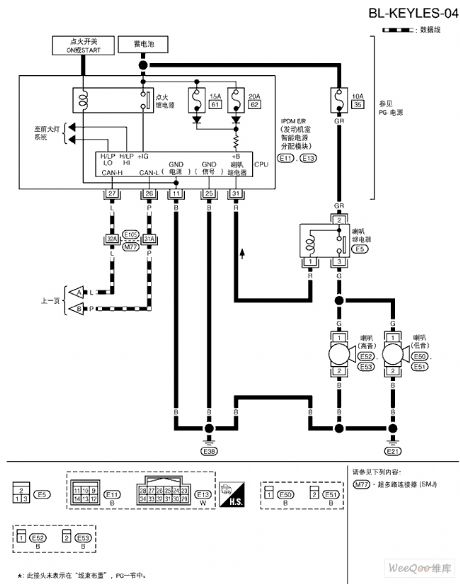
TIIDA-BL Remote Door System Circuit (View)
View full Circuit Diagram | Comments | Reading(861)
TIIDA-AV Navigation System Circuit One
Published:2011/7/20 3:26:00 Author:Joyce | Keyword: TIIDA , AV, Navigation System
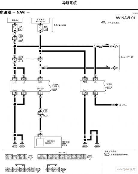
TIIDA-AV Navigation System Circuit (View)
View full Circuit Diagram | Comments | Reading(757)
| Pages:575/2234 At 20561562563564565566567568569570571572573574575576577578579580Under 20 |
Circuit Categories
power supply circuit
Amplifier Circuit
Basic Circuit
LED and Light Circuit
Sensor Circuit
Signal Processing
Electrical Equipment Circuit
Control Circuit
Remote Control Circuit
A/D-D/A Converter Circuit
Audio Circuit
Measuring and Test Circuit
Communication Circuit
Computer-Related Circuit
555 Circuit
Automotive Circuit
Repairing Circuit