
Circuit Diagram
Index 568
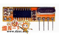
ASK/OOL Small-Size Receiving Module RXB14
Published:2011/8/9 18:08:00 Author:Vicky | Keyword: ASK/OOL Small-Size Receiving Module
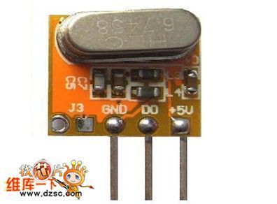
This RF wireless high-frequency receiving module, RXB14, is of high sensitiveness, which reaches -107dBm. The size is very small. It adopts ASK receiving mode, which is available for remote control, far - end control, remote control vehicle, data transmission, anti-theft alarm, home appliance control, wireless toy, vehicle-burglar alarm, wireless backup radar, remote garage gate control , remote motor-driven curtain, flexible door , remote strobe control. It is also an ideal choice GSM/GPS vehicular system set, industry control and systems of high complicated environmental requirement. It can take the place of infrared receptor. It can receive signals from omnidirectional direction and is easy to be added to general remote controls.
Key Feature:
Low-price 315/433.92/ receiving module
Built-in AGC
Low working voltage: 3.0V~5.5V
Low current: 5.7mA
High sensitiveness: -112dBm
Working temperature: -20℃~+85℃
Size of the appearance: 12×10.5×5mm(small size) (View)
View full Circuit Diagram | Comments | Reading(715)
Circuit Diagram of adding visual judgment function to telephone ringing
Published:2011/8/9 18:18:00 Author:Vicky | Keyword: visual judgment function , telephone ringing
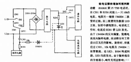
HA868(Ⅲ) P/ TSD telephone, adds a resistance of 10K Ω indirectly between C301 and R301, and connects the anode of diode IN4004 with the other side of the resistance while connects the cathode of the diode with the anode of LED. It is shown by dotted line in the picture. When the telephone works, the current goes through R201 and make the LED lighted. Because IN4004 is reversely biased, and prevents the current from flowing to ringing circuit, the revised part has no affection towards working indication light. When it starts ringing, the ring flows through C301, resistance of 10KΩ and diode IN4004, and becomes a loop via LED and D304. LED then twinkles and gives out light. Since the shunt of the ringing indication is very small, the ring is obviously affected. (View)
View full Circuit Diagram | Comments | Reading(1327)
Ring current generator circuit diagram
Published:2011/8/9 18:20:00 Author:Vicky | Keyword: ring, current generator
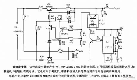
Ring current generator
The ring current generator can produce a ringing current voltage of 75-90V and 25Hz±5HZ. It is available to be used for vibrating ring in communication devices, for example, carrier, ultrahigh frequency, wire telephone. It can also be used as ring in special telephone for dispatchers, repairmen, operators on duty and other users.
The power tube MJ3340 and MJE 350 in the circuit need suitable radiator to protect the power amplification tube and improve the work efficiency. (View)
View full Circuit Diagram | Comments | Reading(4420)
Circuit diagram of auto-adjustment for the telephone ring
Published:2011/8/9 18:22:00 Author:Vicky | Keyword: auto-adjustment , telephone ring
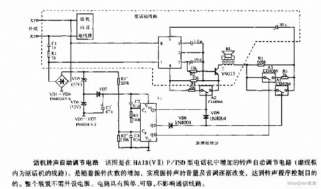
Auto-adjustment circuit of the telephone ring
The above picture is the auto-adjustment circuit added into the HA18(ⅤⅡ) P/ TSD type telephone (the circuit within the dotted frame is the original circuit of the telephone.). With the increasing numbers of the ring times, the gradual change of the ring volume and tone can be achieved and also the goal of control thr ringing procedure can be reached. The whole device needs no peripheral power supply. The circuit is simple and reliable. In addition , it does not affect the communication line. (View)
View full Circuit Diagram | Comments | Reading(1266)
Circuit diagram of constant-current-source type power supply and off-hook detection
Published:2011/8/9 18:23:00 Author:Vicky | Keyword: constant-current-source , power supply , off-hook detection
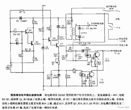
Circuit diagram of constant-current-source type power supply and off-hook detection
The circuit is used for HJD05 –type switching board. The direct current path is + 48V, and the resistances R5, R1, and the transistors Q1, Q3 constitutes a supply circuit in the positive end of the power supply. The upper end of R3 is connected with a end of the extension’s telephone line via a relay. The b end of the extension’s telephone line is connected to upper end of resistance R14 via a relay. The b end then is connected with 0V end of the power supply via R14, transistors Q3, R16, R15, R5, and R7, and the luminous diodes of the photoelectric coupler, which constitute the supply circuit in the negative end of the power supply. (View)
View full Circuit Diagram | Comments | Reading(3208)
Light-Operated Ring Circuit Diagram
Published:2011/8/9 18:24:00 Author:Vicky | Keyword: Light-Operated Ring

Light-Operated Ring Circuit
Average telephone ring circuit is composed of KA2401 and peripheral components. When adding light-operated ring circuit, just connects the part “X” in picture a with light-operated circuit in picture b. When there is input of AC ring signal into the exterior line, the pin 8 of KA2401 outputs ring signal of two tones. In the daytime, light sensitive tube 3DU has low resistance value, the SCR is conducted, and the volume of ring is relatively higher; in the evening, when there is no light, the resistance value of 3DU is very high (several megohms), the ring signal is weakened by R2 before passing through , so the volume of ring is much lower. (View)
View full Circuit Diagram | Comments | Reading(1896)
Superheterodyne Receiving Module RXB7
Published:2011/8/9 17:49:00 Author:Vicky | Keyword: Superheterodyne Receiving Module
This RF wireless high-frequency receiving module, RXB7, is of high sensitiveness, which reaches -110dBm. It adopts ASK receiving mode, which is available for remote control, far- end control, remote control vehicle, data transmission, anti-theft alarm, home appliance control, wireless toy, vehicle-burglar alarm, wireless backup radar, remote garage gate control , remote motor-driven curtain, flexible door , remote strobe control. It is also an ideal choice GSM/GPS vehicular system set, industry control and systems of high complicated environmental requirement. It can take the place of infrared receptor. It can receive signals from omnidirectional direction and is easy to be added to general remote controls.
Key Feature:
315/433.92/868/914.5MHz receiving module
Built-in AGC
Low working voltage: 3.0V~5.5V
Low current: 315MHZ/433.92MHZ (it is available to be connected to power-saving mode in the outside and the start-up time is 250µs; the low-current shutdown mode is 30nA, which effectively save power)
High sensitiveness: -110dBm
Working temperature: -40℃~+85℃
Size of the appearance: 32×12×5mm
(View)
View full Circuit Diagram | Comments | Reading(581)
Superheterodyne Receiving Module RXB8
Published:2011/8/9 17:50:00 Author:Vicky | Keyword: Superheterodyne Receiving Module
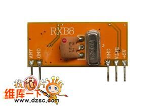
Features:
(1) The sensitiveness is up to -114dbm, and its receiving distance is twice over the average receiving module
(2) It has a reasonable receiving bandwidth, and strong capability of resisting disturbance, which is available in every kind of environment
(3) It owns good capability to collect or release radiation resistance, and meet the detection standard of FCC and CE
(4) It has good shielding function, so that the performance is seldom affected under whatever the assembling environment
(5) It has good local oscillating radiation resistance capability, and enables several modules to work together without disturbing each other or affecting receiving distance
(6) It adopts SWA local oscillator, which has stable performance and is available under a wide range of temperature
(7) It saves power, and only consumes receiving power of about 10mA when it works under 5V power supply.
(8) It is available from 250 to 450MHZ, and the frequency points are easy to adjusted; the supply cycle of the goods is also short
(9) Direct interface for monolithic, and easy to realize
(10) It has good consistency and small size
(11) The transmission rate can reach up to 20kbps (View)
View full Circuit Diagram | Comments | Reading(836)
Superheterodyne receiving module RXB9
Published:2011/8/9 17:51:00 Author:Vicky | Keyword: Superheterodyne receiving module
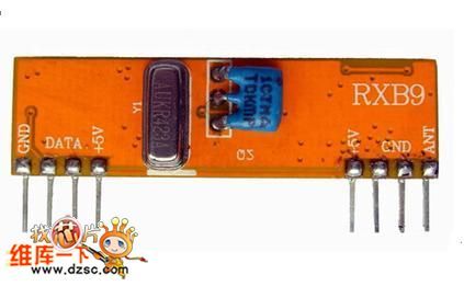
Features:
(1)The sensitiveness is up to -114dbm, and its receiving distance is twice over the average receiving module
(2)It has a reasonable receiving bandwidth, and strong capability of resisting disturbance, which is available in every kind of environment
(3)It owns good capability to collect or release radiation resistance, and meet the detection standard of FCC and CE
(4)It has good shielding function, so that the performance is seldom affected under whatever the assembling environment
(5)It has good local oscillating radiation resistance capability, and enables several modules to work together without disturbing each other or affecting receiving distance
(6)It adopts SWA local oscillator, which has stable performance and is available under a wide range of temperature
(7)It saves power, and only consumes receiving power of about 10mA when it works under 5V power supply.
(8)It is available from 250 to 450MHZ, and the frequency points are easy to adjusted; the supply cycle of the goods is also short
(9)It has direct interface for monolithic, and is easy to realize
(10) It has good consistency and small size
(11)The transmission rate can reach up to 20kbps (View)
View full Circuit Diagram | Comments | Reading(568)
Superheterodyne Receiving Module RXB12
Published:2011/8/9 17:52:00 Author:Vicky | Keyword: Superheterodyne Receiving Module
This RF wireless high-frequency receiving module, RXB12, is of high sensitiveness, which reaches -107dBm. The size is very small. It adopts ASK receiving mode, which is available for remote control, far - end control, remote control vehicle, data transmission, anti-theft alarm, home appliance control, wireless toy, vehicle-burglar alarm, wireless backup radar, remote garage gate control , remote motor-driven curtain, flexible door , remote strobe control. It is also an ideal choice GSM/GPS vehicular system set, industry control and systems of high complicated environmental requirement. It can take the place of infrared receptor. It can receive signals from omnidirectional direction and is easy to be added to general remote controls.
Key Feature:
Low-price 315/433.92/ receiving module
Built-in AGC
Low working voltage: 3.0V~5.5V
Low current: 5.7mA
High sensitiveness: -107dBm
Working temperature: -20℃~+85℃
Size of the appearance: 30×9×5mm (View)
View full Circuit Diagram | Comments | Reading(659)
Single-button Ten-grade Timing Alarming Switch Circuit Diagram
Published:2011/8/9 17:56:00 Author:Vicky | Keyword: Single-button, Ten-grade, Timing Alarming Switch

The time presetting circuit of the timing alarming switch is composed of decimal counter/decoder CD4017, electronic switch CD4066 and the peripheral circuits.IC1 has ten decoding output ends,Q0~Q9. They present high level in turn with the continuous input of 14 pin clock pulse. This circuit takes use of the feature of CD4017, and connects each of the output ends Q0~Q9 with the control end C of electronic switches IC2a~IC4b respectively so as to control these ten the electronic switches and enable the resistances of different resistance value to be connected with the timing circuit, which can reach the goal of changing the timing time. The power supply charges the capacitance C1 via the charging resistor chosen by S1. When the time is over, IC5 (NE555) spins, the control relay cuts off the laden power supply, and meanwhile the trigger IC6 gives out rub-a-dub sound to tell it’s time up. (View)
View full Circuit Diagram | Comments | Reading(1012)
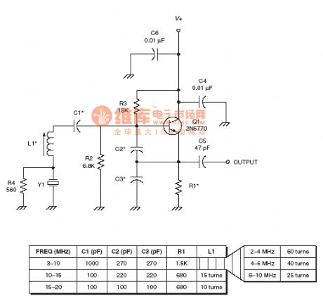
the Oscillator circuit of the radio frequency :Butler oscillator RF circuit
Published:2011/8/12 22:09:00 Author:Ariel Wang | Keyword: Oscillator, radio frequency , Butler

View full Circuit Diagram | Comments | Reading(928)
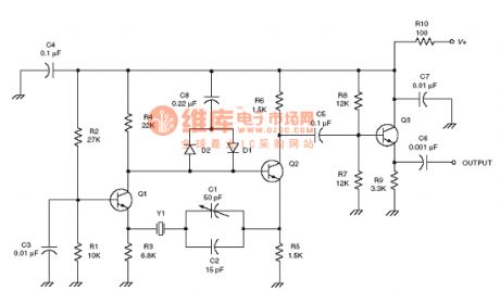
the Oscillator circuit of the radio frequency :Butler overtone crystal oscillator RF circuit
Published:2011/8/12 22:30:00 Author:Ariel Wang | Keyword: oscillator, radio frequency , Butler, overtone, crystal

View full Circuit Diagram | Comments | Reading(1465)
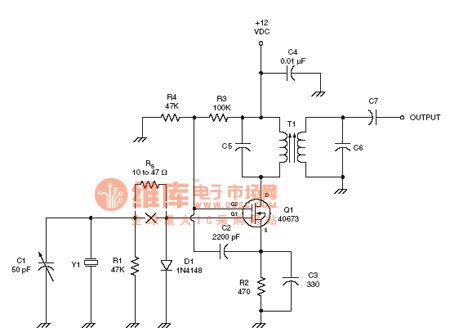
the oscillator circuit of the radio frequency :Higher overtone crystal oscillator RF circuit
Published:2011/8/12 22:32:00 Author:Ariel Wang | Keyword: oscillator, Higher overtone, crystal , RF

View full Circuit Diagram | Comments | Reading(832)
the Oscillator circuit of the radio frequency :Impedance inverting colpitts crystal oscillator RF circuit
Published:2011/8/12 22:35:00 Author:Ariel Wang | Keyword: oscillator, Impedance, inverting, colpitts, crystal, RF
View full Circuit Diagram | Comments | Reading(1447)
the oscillator circuit of the radio frequency :Improved Butler oscillator RF circuit
Published:2011/8/13 0:29:00 Author:Ariel Wang | Keyword: oscillator, radio frequency , Improved, Butler
View full Circuit Diagram | Comments | Reading(1240)
the oscillator circuit of the radio frequency :LP Pierce oscillator RF circuit
Published:2011/8/13 0:32:00 Author:Ariel Wang | Keyword: oscillator, LP , Pierce

View full Circuit Diagram | Comments | Reading(710)
the oscillator circuit of the radio frequency :Pierce oscillator RF circuit
Published:2011/8/13 0:34:00 Author:Ariel Wang | Keyword: oscillator, Pierce, RF

View full Circuit Diagram | Comments | Reading(917)
the oscillator circuit of the radio frequency :Tuned Miller oscillator RF circuit
Published:2011/8/13 1:00:00 Author:Ariel Wang | Keyword: oscillator, radio frequency , tuned, miller
View full Circuit Diagram | Comments | Reading(1157)
the absolutely useful switch power supply:the STR41090 power supply(A4)
Published:2011/8/13 6:46:00 Author:Ariel Wang | Keyword: absolutely useful , switch power supply

View full Circuit Diagram | Comments | Reading(801)
| Pages:568/2234 At 20561562563564565566567568569570571572573574575576577578579580Under 20 |
Circuit Categories
power supply circuit
Amplifier Circuit
Basic Circuit
LED and Light Circuit
Sensor Circuit
Signal Processing
Electrical Equipment Circuit
Control Circuit
Remote Control Circuit
A/D-D/A Converter Circuit
Audio Circuit
Measuring and Test Circuit
Communication Circuit
Computer-Related Circuit
555 Circuit
Automotive Circuit
Repairing Circuit