
Circuit Diagram
Index 578
50W Hi-Fi Integrated Audio Power Amplifier (TDA1514A) Circuit
Published:2011/7/17 22:09:00 Author:Robert | Keyword: 50W, Hi-Fi, Integrated, Audio, Power Amplifier

The picture shows the audio integrated power amplifier's typical application circuit composed ofTDA1514A. TDA1514A is a 50W Hi-Fi audio amplification IC produced by the Philips company. Its internal protection circuitsare complete, which means it has not only the general over-heating, output short circuit protection, but also the safe operating area protection. The circuit is also set up a silent switch to suppress the starting noise' appearance. In the circuit's design it is also considered the better ripple rejection and low offset with low thermal resistance. (View)
View full Circuit Diagram | Comments | Reading(5347)
Voltage Waveform Circuit Of Welding Sensor Each Point
Published:2011/7/27 3:22:00 Author:Robert | Keyword: Welding Sensor, Point, Voltage, Waveform
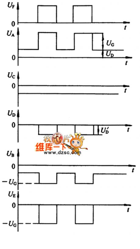
The picture shows the welding sensor each point's voltage waveform circuit. (View)
View full Circuit Diagram | Comments | Reading(1026)
The emission control and air conditioning schematic circuit of Toyota Land Cruiser 70 light-duty off-road vehicle
Published:2011/8/9 19:57:00 Author:Sophia | Keyword: The emission control and air schematic conditioning, Toyota Land Cruiser 70 light-duty off-road vehicle
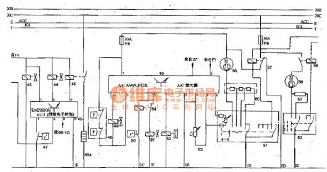
Air conditioning control circuit is mainly to control electromagnetic clutch 52 and the air conditioning blowers 56, 59. Seen from the figure, the blower can be controlled by manpower, and only the blower 56 operating under the premise of air conditioning, compressor 52 are allowed to work.
Air-conditioning amplifier's input signal: A / C thermostat 53, air-conditioning coolant temperature switch 50 (relay 54 is to cut off the circuit of solenoid valve 51, which makes the fast idle speed changed to normal idle speed), dual pressure switch (low voltage lines switches and high-pressure pipeline switch) 48, which can be connected to air-conditioning amplifier control circuit, the supply current flows from F8.)
The Actuating mechanism of air-conditioning amplifier 55 is the compressor magnetic clutch actuator 52 and fast idle solenoid valve. When the current heater motor switch 61 is Connected, if the ambient temperature is above 10 ℃ or domain thermostat temperature is above 5 ℃, and pipeline pressure is normal, then the amplifier connects to the compressor magnetic clutch and air conditioning and refrigeration cycle to make the engine more fuel fast idle. Until the engine temperature rises to a predetermined value, the thermostat switch is closed; the solenoid valve 51 is off, the engine returns to normal idle speed.
(View)
View full Circuit Diagram | Comments | Reading(3485)
STR-6658B power supply thick film hybrid integrated circuit
Published:2011/8/9 19:57:00 Author:Sophia | Keyword: Power supply thick film hybrid integrated

(View)
View full Circuit Diagram | Comments | Reading(1642)
1024KHz temperature compensation crystal oscillator circuit diagram
Published:2011/8/9 19:59:00 Author:Sophia | Keyword: 1024KHz temperature compensation, crystal oscillator
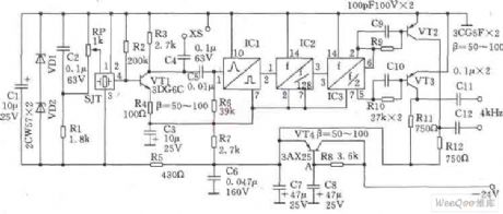
This circuit SJT is 1024kHz temperature compensation crystal oscillator. Circuit theoryis asshown. Because output signal level of the circuit is low, the buffer of follow-up transistor VTl is amplified. VTl base bias resistor R2, the load resistor R3, the emitter resistor R4 are the negative feedback resistors for stablizing VTl DC operating point. Zener diode VDl, VD2, capacitor Cl form stabilivolt and filter circuit to reduce the influency of the supply voltage fluctuations on the frequency of the crystal SJT. Resistors Rl and potentiometer RP TCXO provide bias voltage. regulation of RP can fine-tune the oscillator to reach precise frequency.
(View)
View full Circuit Diagram | Comments | Reading(1812)
Solid-state relay basic wiring schematic diagram
Published:2011/8/8 0:21:00 Author:Sophia | Keyword: Solid-state relay, Wiring

At present, solid-state relay has been applied to different industries. broadly speaking, solid-state relay includes several cpmtrol systems:
temperature control system, miniwatt motor control system, three-phrase electric machine regenerative control system, solenoid value control system, high frenquency system and so on. Butmany beginners and some engineers haven't engaged in these areas, so now I draw a simple wiring diagram for reference. (View)
View full Circuit Diagram | Comments | Reading(6453)
Computer Microphone and JFET-MOSFET earphone power amplifier circuit diagram
Published:2011/8/8 0:23:00 Author:Sophia | Keyword: Computer Microphone, JFET-MOSFET earphone, power amplifier


PC sound card usually possesses microphone input and loudspeaker output, sometimes line input and output. The design of input resistance of dynamic microphone just can be achieved in the scope of 200~600ohms. Sound card can use a common electret microphone to suit this curcuit. a composite amplifier can use two transistor.
when BC413B is working normally, it slightly drives the microphone signal emitter amplifier, next, it comes to the stage of emitter follower, which is necessary. Because that the microphone, curcuit and battery make use of the distance of some sound card, the low output resistance of circuit and shielded cable can ensure to collect the clean signal through the smallest noise pickup. (View)
View full Circuit Diagram | Comments | Reading(2565)
STR-F6454R Switching power supply thick film integrated circuit diagram
Published:2011/8/8 0:23:00 Author:Sophia | Keyword: Switching power supply, thick film integrated circuit

(View)
View full Circuit Diagram | Comments | Reading(1374)
NEC mobile charger circuit diagram
Published:2011/8/4 21:10:00 Author:Sophia | Keyword: NEC mobile charger

NEC mobile phone charger circuit is shown as below When C1 selected 2.2? F/250V AC step-down capacitor, the output current is about 130mA. Mobile phone battery charging time can be easily selected according to the capacity, so the battery will not be damaged. Specific discharge functions can extend nickel-cadmium battery life with the memory effect. Charging power is indicated by the four high-brightness light-emitting diode level indication, which is very intuitive. In the charging circuit, the AC depressurization capacitor and discharge control tube C8550 are delicate components. When we need to maintain these two components, we can use comprehensive similar component to replace them. (View)
View full Circuit Diagram | Comments | Reading(3664)
Touch relay switch circuit diagram
Published:2011/8/4 21:11:00 Author:Sophia | Keyword: Touch relay switch

Touch delay switch circuit formed by the time base NE555 chip.
IC1 is a 555 timer circuit, which also becomes monostablecircuit. Usually because P-side of touching film doesn't have induced voltage, which make capacitor C1 discharge through the 7th foot of 555 , 3-pin output is low level. The relay KS is released, and light does not shine.
When you need to turn on the lights, we just touch the metal P with the hands. The noise signal voltage of the human sense is added from C2 to the trigger terminal of 555, which makes the output of 555 become high from low output, relay KS pull and light lightened. Meanwhile, the first 7 pin interior of 555 within is stoped, then the power charge to C1 through R1, and this is the beginning of time. (View)
View full Circuit Diagram | Comments | Reading(3702)
RP-type ideal diode circuit
Published:2011/8/7 23:40:00 Author:Sophia | Keyword: RP-type, ideal diode
Clamping circuit is difficult to achieve in non-inverting idealized diode circuit. Inevitably the output can be saturated on the negative potential. Thus, the general idealized diode is constituted by the inverting circuit shown in Figure 1. In this circuit, when the input is positive potential, diode D1 is conducted, and OP amplifier output is almost saturated because of the diode forward voltage (-VF). At this point, because of -VF, the diode D1 is against the bias, and the circuit output resistance ro is 10kΩ. (View)
View full Circuit Diagram | Comments | Reading(748)
The symmetrical double T circuit to improve the notch filter circuit
Published:2011/8/7 23:40:00 Author:Sophia | Keyword: symmetrical double T, improve the notch filter

Figure 1 is an example of the symmetrical double-T circuit. Under careful observation, we found that it is circuit synthesis of low-pass filter and high pass filter. In this circuit, usually the ratio of components grounding into the earth adopts 2C and R / 2 method. The reason for this is that the ratio can effectively make the attenuation frequency reach the spike values, but the Q value of this circuit is also dropped to 0.25, zero frequency The composition of the circuit is extremely simple, accoring to the circuit, we can see 2C capacitors is needed. The author's approach improves the cost, we can adopt two capacitors connected in parallel to process. (View)
View full Circuit Diagram | Comments | Reading(2451)
The RC phase-shift circuit with unchanged Output amplitude
Published:2011/8/7 23:42:00 Author:Sophia | Keyword: The RC phase-shift circuit, unchanged Output amplitude

The most commonly used phase shifter phase difference is 90 °. Shown in Figure 1, in the RC phase shift circuit, even the amplitude is allowed down to 3dB, phase shift quantity is 45 °, as in the OP amplifier circuit shown in Figure 1, which is characterized by the phase shift of 0 to 180 °, 180 °to 0 , and the output amplitude does not depend on input frequency. The diagram shows the basic of RC phase circuit, the inverting amplifier of the gain A =- 1. This RC circuit can be connected to the non-inverting input terminal to decide the feedback resistance of inverting gain. If they are the same resistance value, its value can be chosen freely, actually, it is typically chosen to be 10kΩ. (View)
View full Circuit Diagram | Comments | Reading(3436)
Southeast Ling Sheng fog lamp electric systemg circuit
Published:2011/8/6 21:36:00 Author:leo | Keyword: Fog lamp, electric system


View full Circuit Diagram | Comments | Reading(840)
The constant voltage/constant current power resources circuit formed by CW117/CW217/CW317
Published:2011/8/10 19:05:00 Author:leo | Keyword: Constant voltage, constant current, power resources

As the picture shows, it is a constant voltage/constant current power supply circuit. It is made up of extend current part, constant voltage part and constant current part. Two power transistors are parallel connected to form the extending current tube. And R3 is the current limited resistance while R2 is current electric level adjusting device. R is the voltage electric level adjusting device. This power resources can offer the voltage of 1.25 V to 30 V with the current of 0 to 5A. (View)
View full Circuit Diagram | Comments | Reading(3115)
The constant current power resources circuit with adjustable output current formed by CW7805
Published:2011/8/10 19:05:00 Author:leo | Keyword: Constant current, power resources, adjustable output current

View full Circuit Diagram | Comments | Reading(2650)
The absolute sine wave inverted power supply circuit made by MCU
Published:2011/8/10 19:06:00 Author:leo | Keyword: Sine wave, MCU, inverted power supply

Absolute sine wave inverted power supply circuit made by MCU (View)
View full Circuit Diagram | Comments | Reading(1600)
ZDD-12-160 full auto multi-functional inverted power supply circuit
Published:2011/8/10 19:06:00 Author:leo | Keyword: Full auto, multi-function, inverted power supply


ZDD-12-160 full auto and multi-functional inverted power supply pre-circuit
ZDD-12-160 full auto and multi-functional inverted power supply final stereo circuit
(View)
View full Circuit Diagram | Comments | Reading(841)
The low power constant voltage power resources circuit formed by HIP5600(NO transformer)
Published:2011/8/10 19:07:00 Author:leo | Keyword: Low power, constant voltage, power resources, no transformer


The constant voltage power resources circuit has many unique features:1.DC work voltage can reach 400V2.AC work voltage can reach 280 V3.It can be connected to two outer resistances. Its DC input voltage is 1.2 V and can be adjusted from VIN to 50 V. The input current can be adjusted from 1 mA to 30 mA.4. It has its own cooler and does not need outer protecting circuit.
(View)
View full Circuit Diagram | Comments | Reading(1295)
High-voltage Electrostatic Generator (the 1st)
Published:2011/7/29 4:32:00 Author:Felicity | Keyword: High-voltage Electrostatic, Generator

Work of the circuit
The circuit consists of power Switch power transformer T, rectifier diode VDl-VD9, capacitors Cl-C9, resistors R1-R4, a voltmeter PV and ammeter PA. (It is showed in the picture 8-115.)
Turn on power switch s. the 220V AC voltage is set-up by the power transformer. The 9 doubler rectifying circuit consists of VDl-VD9 and Cl-C9. The voltage is 9 doubler rectified by the circuit. It then produces 100LV DC voltage. The voltage separates into two parts. One is limited by M and then outputted. The other one is limited by R1-R3. PV shows the value of outputting voltage.
When the circuitcomponentsinstalled,you should useepoxytosealfillingprocessto preventdischargebetweenthe variouscomponents. (View)
View full Circuit Diagram | Comments | Reading(5764)
| Pages:578/2234 At 20561562563564565566567568569570571572573574575576577578579580Under 20 |
Circuit Categories
power supply circuit
Amplifier Circuit
Basic Circuit
LED and Light Circuit
Sensor Circuit
Signal Processing
Electrical Equipment Circuit
Control Circuit
Remote Control Circuit
A/D-D/A Converter Circuit
Audio Circuit
Measuring and Test Circuit
Communication Circuit
Computer-Related Circuit
555 Circuit
Automotive Circuit
Repairing Circuit