
Circuit Diagram
Index 576
TIIDA-AV Navigation System Circuit Two
Published:2011/7/20 3:27:00 Author:Joyce | Keyword: TIIDA , AV, Navigation System

TIIDA-AV Navigation System Circuit (View)
View full Circuit Diagram | Comments | Reading(775)
TIIDA-AV Navigation System Circuit Three
Published:2011/7/20 3:28:00 Author:Joyce | Keyword: TIIDA, AV , Navigation System

TIIDA-AV Navigation System Circuit (View)
View full Circuit Diagram | Comments | Reading(786)
TIIDA-BL Remote Door System Circuit Two
Published:2011/7/20 3:28:00 Author:Joyce | Keyword: TIIDA, BL , Remote Door System
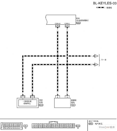
TIIDA-BL Remote Door System Circuit (View)
View full Circuit Diagram | Comments | Reading(746)
TIIDA-AV Navigation System Circuit Four
Published:2011/7/20 3:29:00 Author:Joyce | Keyword: TIIDA, AV, Navigation System

TIIDA-AV Navigation System Circuit (View)
View full Circuit Diagram | Comments | Reading(818)
TIIDA-AV Audio Circuit
Published:2011/7/20 3:29:00 Author:Joyce | Keyword: TIIDA , AV, Audio

TIIDA-AV Audio Circuit (View)
View full Circuit Diagram | Comments | Reading(814)
PHILIPS LCD DC/DC Convertor Circuit
Published:2011/7/14 0:19:00 Author:Joyce | Keyword: PHILIPS , LCD, DC/DC , Convertor

PHILIPS LCD DC/DC convertor circuit is as shown . (View)
View full Circuit Diagram | Comments | Reading(897)
High-precision Delay Timer Circuit
Published:2011/7/21 21:56:00 Author:Joyce | Keyword: High-precision Delay, Timer
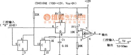
As shown in the figure is a high-precision delay timer circuit. In the figure, Rt, Ct are timing elements, with timing time T being RtCt (s). Changing the values of Rt, Ct can adjust the time of timing, but by doing so, the stability will get worse, so, usually it is achieved by adjusting the comparative level of the comparator, that is to say, by adjusting RV1 in the figure.
This circuit can improve the precision of timing. It requires comparator, capacitance, resistance of stable performance and switch mode with no disorder voltage, low on resistance and high cut-off resistance. (View)
View full Circuit Diagram | Comments | Reading(1292)
Please-Close-the-Door Language Integrated Circuit
Published:2011/7/21 21:59:00 Author:Joyce | Keyword: Please Close the Door, Language , Integrated
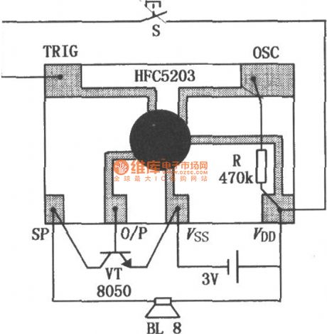
HFC5203A is large-scale CMOS integrated circuit, storing a female voice please close the door . The pronunciation is clear and the peripheral circuit is simple. With level and do-not-keep- triggering mode, it can be widely used in banks, stores, security departments, air conditioning rooms and electric refrigerators to give reminders. The typical application circuit of HFC5203A is as shown in the figure.
(View)
View full Circuit Diagram | Comments | Reading(1445)
Back-up-Attention-Please Language Integrated Circuit
Published:2011/7/21 22:00:00 Author:Joyce | Keyword: Back up, Attention Please , Language , Integrated
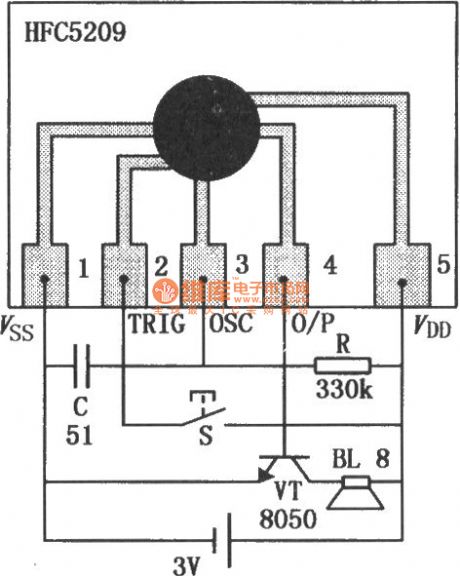
HFC5210 can send out warning —— back up, attention please .This circuit has good performance, clear pronunciation and a simple peripheral circuit. It is one of the most commonly used warning circuits for backing up. Its typical application circuit is as shown in the figure. (View)
View full Circuit Diagram | Comments | Reading(948)
800Hz Oscillator Circuit
Published:2011/8/2 1:31:00 Author:Joyce | Keyword: 800Hz, Oscillator

As shown in the figure is the 800 Hz oscillator characteristic of its simple circuit, high frequency accuracy and stable output level. It consists of four-operational amplifier integrated packages A1 ~ A3 (LM324) and tuning fork SJT (YYZ-2-800 Hz). When SJT produces 800 Hz oscillation signal feedback to the two-stage operational amplifier composed of A1 and A2 ,the signal is output by feet ⑦ of A2 . Then it will become positive feedback frequency signal after going through resistance R5, SJT .The 800 Hz signal will be amplified again by one-stage A3. Then the signal will be sent to potentiometer RP`s adjustable end (Uo) by A3`s feet ⑧ to become 800 Hz sine wave signal. Adjusting potentiometer RP can meet the requirement of output level of 0 dB / 600 Ω the output level, and the adjustable scope is ± 3 dB. (View)
View full Circuit Diagram | Comments | Reading(1273)
High Quality Low Frequency Signal Generator Circuit Composed of F007
Published:2011/8/2 1:31:00 Author:Joyce | Keyword: High Quality, Low Frequency , Signal , Generator

As shown in the figure is a high quality low frequency signal generator circuit characteristic of well-performed fixed amplitude, large output power and little wave distortion. It is a kind of ideal low frequency signal source. In the figure, operational amplifiers A and its feedback network constitute a typical venturi oscillator, whose oscillation frequency is:f0 = 1/2π RCA2 . The output end is connected with complementary push-pull power amplifier OCL to improve the load capacity of the circuit. Operational amplifier A1 is connected into a negative half-wave amplifier, and composes a negative feedback fixed amplitude circuit with W1, R4, C1, and T1 ect.
(View)
View full Circuit Diagram | Comments | Reading(961)
10-gear Frequency Signal Generator Circuit
Published:2011/8/2 1:32:00 Author:Joyce | Keyword: 10-gear Frequency , Signal Generator

Usually, the general frequency signal generator is designed to have the whole frequency range which can be adjusted continuouslywhen in use. But in fact, the common test frequencies we use are only a few. The following frequency signal generator introduced has ten fixed frequency gears most commonly used, from which the user can choose according to his/her need. The frequency signal generator is composed of a digital gear switch and ten fixed frequency signal generator as shown in the figure. (View)
View full Circuit Diagram | Comments | Reading(814)
Touch Biostable Controller Circuit
Published:2011/8/2 1:30:00 Author:Joyce | Keyword: Touch , Biostable , Controller
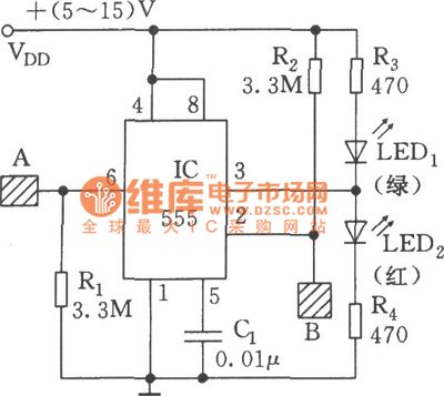
Feet 6 and 2 of 555 are connected with the inphase and inverse input ends of comparator A1 and A2 within the substrate respectively to control its state of reset and set to change its output state. Touching metal A will reset 555, and LED (green) will be enlightened and LED1 (red) will go out; Touching metal 8 will enlighten LED2 and quench LED1 . If the relay is changed over, the control of on-off of power supply for the executive circuit can be achieved.
(View)
View full Circuit Diagram | Comments | Reading(844)
Capacitive Switch Circuit
Published:2011/8/2 1:30:00 Author:Joyce | Keyword: Capacitive , Switch
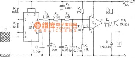
As shown in the figure, the switch circuit is composed of capacitive oscillator, integrating network, comparative circuit and relay control circuit. When the human body gets close to the metal plate, inductive capacitance over the ground will increase, so that the astable multivibrator formed of 555 will start oscillation or have its oscillation frequency changed. The output alternating square wave will be added to the inphase end of comparator IC2 (LM324) after going through the three-level integrating network to be compared with the reference voltage which has been set. Then it will output a transitioning negative pulse, VT1 will break over, and K will actuate to connect the load circuit. Conversely, the load circuit will be disconnected. Selection of the induction plate should make oscillation frequency be no less than several thousand kHz. (View)
View full Circuit Diagram | Comments | Reading(2131)
Automatic night lighting light circuit composed of the μA555
Published:2011/8/2 4:22:00 Author:Christina | Keyword: Automatic lighting, light

The automatic night lighting light circuit is as shown in the figure. This circuit is composed of the photoelectric switch, the multivibrator.etc. The multivibrator is composed of the W1, R5, R6, C1 and 555, the oscillation frequency f=1.44/(Rw1+R5+2R6)C1, the frequency is about 2-10 seconds, you can get the corresponding frequency by adjusting the potentiometer W1.
In the photoelectric switch, the BG1(3DU5) is the phototransistor, it has different resistance values in different illuminations. In the day time, the phototransistor has the low resistance because of the illumination, so the BG2 cuts off, the BG3 conducts, the SCR cuts off, the oscillator stops, the indicator light will not turn on.
(View)
View full Circuit Diagram | Comments | Reading(807)
The CMOS logic probe circuit
Published:2011/7/18 6:35:00 Author:Christina | Keyword: CMOS, logic probe
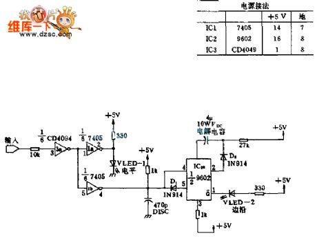
This circuit is the fault diagnosis tool, you need to connect it to the microprocessor to display the state of important port. When the TTL input is 1 , the LED turns on; when the TTL input is 0 , the LED will not turn on. When the input is from 1 to 0 or 0 to 1 , the edge LED-2 turns on just one time. The input port uses the CMOS inverting buffer 3a to prevent the probe affects the work of microprocessor.
(View)
View full Circuit Diagram | Comments | Reading(1251)
The Low noise sine wave crystal oscillator circuit
Published:2011/7/18 6:35:00 Author:Christina | Keyword: Low noise, sine wave, crystal oscillator

The Low noise sine wave crystal oscillator circuit is as shown:
(View)
View full Circuit Diagram | Comments | Reading(1179)
The circuit of the differential amplifier
Published:2011/7/18 6:36:00 Author:Christina | Keyword: Differential amplifier

The Differential amplifier circuit is as shown:
(View)
View full Circuit Diagram | Comments | Reading(611)
GL3274 (TV) infrared remote control receiving preamplifier circuit
Published:2011/8/4 1:28:00 Author:Christina | Keyword: TV, infrared, remote control, receiving, preamplifier circuit
The GL3274 has the same functions and pin arrangement with the CX20106A, so they can exchange directly. The technical characteristics, absolute maximum ratings, main electrical specifications, logic diagram and typical application circuits of GL3274 can reference the CX20106A's.
(View)
View full Circuit Diagram | Comments | Reading(637)
MCl45027 general infrared, ultrasonic or RF remote control receiving decoder circuit
Published:2011/7/18 6:35:00 Author:Christina | Keyword: general, infrared, ultrasonic, RF, remote control, receiving decoder


The MCl45027 is designed as one kind of general red-needle line, ultrasonic or RF remote control receiving decoder circuit. The internal circuit is composed of the sequence generator, the logic control circuit, the 4-bit shift register, the data extraction circuit and the latch circuit.etc.
Features
It uses the binary or ternary to find the address;The ternary addressing coding has the maximum species;The receive media can be the infrared, ultrasonic in the error detection;The permissible error range of the external components can be 5%;Standard B series input and output characteristics;The power voltage is 4.5-18V;Plastic DIP or SOG package;The matching model is MCl145026.
(View)
View full Circuit Diagram | Comments | Reading(619)
| Pages:576/2234 At 20561562563564565566567568569570571572573574575576577578579580Under 20 |
Circuit Categories
power supply circuit
Amplifier Circuit
Basic Circuit
LED and Light Circuit
Sensor Circuit
Signal Processing
Electrical Equipment Circuit
Control Circuit
Remote Control Circuit
A/D-D/A Converter Circuit
Audio Circuit
Measuring and Test Circuit
Communication Circuit
Computer-Related Circuit
555 Circuit
Automotive Circuit
Repairing Circuit