Amplifier Circuit
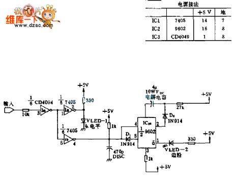
The CMOS logic probe circuit
Published:2011/7/18 6:35:00 Author:Christina | Keyword: CMOS, logic probe | From:SeekIC

This circuit is the fault diagnosis tool, you need to connect it to the microprocessor to display the state of important port. When the TTL input is 1 , the LED turns on; when the TTL input is 0 , the LED will not turn on. When the input is from 1 to 0 or 0 to 1 , the edge LED-2 turns on just one time. The input port uses the CMOS inverting buffer 3a to prevent the probe affects the work of microprocessor.
Reprinted Url Of This Article:
http://www.seekic.com/circuit_diagram/Amplifier_Circuit/The_CMOS_logic_probe_circuit.html
Print this Page | Comments | Reading(3)

Article Categories
power supply circuit
Amplifier Circuit
Basic Circuit
LED and Light Circuit
Sensor Circuit
Signal Processing
Electrical Equipment Circuit
Control Circuit
Remote Control Circuit
A/D-D/A Converter Circuit
Audio Circuit
Measuring and Test Circuit
Communication Circuit
Computer-Related Circuit
555 Circuit
Automotive Circuit
Repairing Circuit
Code: