
Circuit Diagram
Index 577
Sound excitation switch circuit
Published:2011/7/18 6:36:00 Author:Christina | Keyword: Sound, excitation, switch circuit

This circuit can be used as the sensor of the anti-theft alarm, and it can be used to open the monitor recorder to record the conversation. You can get the required sensitivity by adjusting R8. LM229 is the quad comparator, the first part A1 can be used in the amplification and the wave detection, the gain is 100; A2 compares the DC output of A1 with the selected reference level of R8, the output can trigger the Q1 to produce the 200mA load current and turns on the light-emitting diode.
(View)
View full Circuit Diagram | Comments | Reading(737)
High input voltage voltage-stabilization circuit
Published:2011/7/13 6:42:00 Author:Christina | Keyword: High input voltage, voltage-stabilization


The maximum input voltage-stabilization circuit can be used in the condition of the input voltage, itis higher than the rated voltage of the voltage stabilizer, the high partial pressure power transistor is connected in the input circuit. The resistance value of R1 can be comfirmed by this formula:
In this formula:
Vi--input voltage;VZ--voltage stabilization value of the voltage stabilization diode;Io--the maximum output current of the integrated voltage stabilizer;β--current amplification coefficient of the semiconductor transistor.
(View)
View full Circuit Diagram | Comments | Reading(1397)
The Quartz crystal oscillator circuit
Published:2011/7/13 6:43:00 Author:Christina | Keyword: Quartz crystal, oscillator


The oscillator that is composed of the quartz crystal can be divided into two kinds: the parallel resonant type crystal oscillator and the series resonant type crystal oscillator. The parallel resonant type crystal oscillator and the AC equivalent circuit of it are as shown in figure 1, if the quartz crystal is equivalent to the inductance LD, this circuit is the three-point capacitor oscillator, and only when the frequency is in the range of fo to f∞, the quartz crystal will present the inductance characteristics.
Figure 1 The parallel resonant type crystal oscillator and the AC equivalent circuit
Figure 2 shows the series resonant type crystal oscillator circuit and the AC equivalent circuit of it.
Figure 2 The series resonant type crystal oscillator circuit and the AC equivalent circuit
(View)
View full Circuit Diagram | Comments | Reading(2285)
Thyristor SCR Controlled Rectifier Circuit
Published:2011/8/4 0:08:00 Author:Robert | Keyword: Thyristor, SCR, Controlled, Rectifier


The controlled rectifier circuit's function is changing the AC power to the voltage-controlled DC power. The picture shows the single-phase half-controlled bridge rectifier testing circuit. The main circuit is made up of load RL (lamp) and thyristor T1. The trigger circuit is single-junction transistor T2 and a RC-bridge phase-shift trigger circuit which is made up of some RC elements. By change the thyristor T1's conduction angle it could adjust the main circuit's controlled output rectified voltage (or current)'s value. This could be seen from the variation of the brightness of the lamp load. The thyristor's conduction angle's value is determined by the trigger frequency f which could be calculated from the formula of f=(1/RC)ln(1/1-η). (View)
View full Circuit Diagram | Comments | Reading(1178)
Remote Temperature-Measurement Circuit Composed Of Intelligent Remote Thermal Fan Controller ADT7460
Published:2011/7/14 10:10:00 Author:Robert | Keyword: Remote, Temperature-Measurement, Intelligent, Thermal, Fan, Controller


The remote temperature sensor is composed of ADT7460 with two transistors. As the transistor's emitter voltage is proportional to temperature, this feature could be used to measure the remote temperature. The remote temperature measurement circuit is shown in the picture. The CPU shown in the picture has the temperature-measurement transistor itself. It is equivalent to a 2N3906 PNP transistor. If using the discrete transistor, the collector polar can not be connected to ground and it should be connected to the base polar to be used as diode. If using the NPN transistor, it should connect the base polar to the D+ port, and connect the emitter polar to the D- port. If using the PNP transistor, it should connected the emitter polar to D+ port and connected the base polar to the D- polar. The picture shows the 2N3904 type NPN transistor and 2N3906 type PNP transistor's wiring mode. (View)
View full Circuit Diagram | Comments | Reading(718)
Sanhe Brand Anti-Theft Door Talkback Doorbell Analysis Circuit
Published:2011/8/7 21:54:00 Author:Robert | Keyword: Sanhe, Anti-Theft, Door, Talkback, Doorbell, Analysis
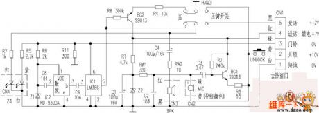
The corridor anti-theft door is the public protection facilities of the urban families. Its talkback doorbell would offen have faults in house decoration and normal using. This article introduces the Sanhe brand SH25 type anti-theft door talkback doorbell (indoor device) working principle which would be reference for maintaining this device and other equivalent products. The circuit is shown in the picture (in the picture the voltage marked with CN1 is the practically tested voltage when open circuit).1.Visitors pressing the button to call the master. When the visitors press the corresponding room number's doorbell switch, the CN1's pin 3 would send DC voltage to supply the working voltage for the IC1 through R11 for voltage divider. And the voltage would be bucked through R5 that indicates the working mode by Z3. Also it is changed to be 3V voltage as the working power of the musical chip IC2 (KD-9300A) through R8's voltage step-down and Z1's voltage regulator. At the same time the C8 would complete the triggering. The IC2 would generate the doorbell's calling signal and then send to the tone amplifier IC1 (LM386) for amplification. And then it would output from the pin 5 and is send to the headphone for sounding through the key switch, C4, RW2. Thus it completes the doorbell calling. (View)
View full Circuit Diagram | Comments | Reading(1321)
Simple And Practical Voice-Controlled Electronic Doorbell Circuit
Published:2011/8/4 0:35:00 Author:Robert | Keyword: Simple, Practical, Voice-Controlled, Electronic, Doorbell

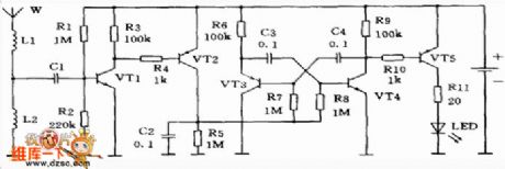
If using this circuit as doorbell circuit, it needn't to install the button switch on the door. The visitors could just knock the door, and the doorbell would sound. The circuit is shown in the picture.
The greatest feature of the circuit is using the loudspeaker as vibration input and also the doorbell sound output.
The transistor V2, potentiometer KP and capacitor C2 make up the control circuit. The V1, V3, R2, C1 make up a complementary oscillator. When the switch S is closed and connected to the power, the power would charge the C2 through the C2, V2's BE junction and loudspeaker BL. The larger peak charging current make V2 saturated and conducted, which clamps the V3's collector polar's voltage level. After the C2's charging, the power would supply the base polar current for V2 through KP, thus it would maintain V2's critical saturation status and make the oscillator not work. (View)
View full Circuit Diagram | Comments | Reading(2199)
Mobile Phone Sensor-900mhz RF Indicator Circuit
Published:2011/8/7 21:53:00 Author:Robert | Keyword: Mobile Phone Sensor-900mhz RF Indicator Circuit
When the mobile phone is in the standby mode and receives the calling signal from the base station, it would transmitter the answer signal. So that the mobile phone's antenna would also have a short time while the RF signal is sending. At this time, is there is a micro sensor beside the mobile phone, it would flash the red light. Some other kinds of sensors could also have the music. By the analysis of the sensor circuit, it is found that it is practically a 900MHz RF indicator. Here the analysis of its working principle is introduced.The 900MHz RF indicator's principle circuit is shown in the picture. The RF signal is received by the spring steel wire L1 which is used as the antenna (w) (L2 is a current-limiting coil with only one cycle). The signal then is sended to VT1 for amplification through C1. The VT1 is in the critical conduction mode at the functions of bias resistor R1 and R2. When no signal the VT1's collector polar is in high voltage level to make the PNP tube VT2 closed. So the multivibrator would not work which is made up of VT3 and VT4. (View)
View full Circuit Diagram | Comments | Reading(2497)
Sound Control Toy Kitten Circuit
Published:2011/8/7 21:53:00 Author:Robert | Keyword: Sound, Control, Toy, Kitten

The sound control toy kitten circuit is shown in the picture. It is made up of two parts which are sound control switch and kitten mew generator. The microphone BM is a sound wave receiver. When it receives the applause sound wave signal, it would output corresponding electric signal to the transistor VT1's base polar for amplification through the capacitor C1. After amplification the signal would output from the VT1's collector polar and be added on the kitten mew IC KD-5605's trigger port through the capacitor C2. Then it would trigger the IC to work. The IC would outpout three times of kitten mew sound which would be amplified by the transistor VT2 and then impulse the small electromagnetic buzzer BL to sound. And also it would drive two LEDs (LED1, LED2) to have the synchronized flash with the kitten mew sound. (View)
View full Circuit Diagram | Comments | Reading(1772)
Flashing Musical Gyroscope Circuit
Published:2011/8/7 21:53:00 Author:Robert | Keyword: Flashing, Musical, Gyroscope

The picture shows the flashing musical gyroscopic circuit. It is made up of musical IC UM66T19L and multi-color LED LED1~LED4. When the gyro is in the rotation mode, because of the function of centrifugal force, the centrifugal switch S1 is connected and the power is added on the four LED directly to make they light. Also the IC1 is connected to the power, the buzzer BL would sound the music. The centrifugal switch S could be self-made by using the elastic metal sheet. It needs to be adjusted for many times and thus it could get a good performance. Also the gyro is a rotated moving object, its overall balance is very important. So the PCB's layout should not only be left-and-right symmetrical, but also should consider the weight balance in the vertical direction. (View)
View full Circuit Diagram | Comments | Reading(2050)
Ultrasonic Liquid Level Indicator Circuit Composed Of NE555
Published:2011/8/7 21:57:00 Author:Robert | Keyword: Ultrasonic, Liquid Level, Indicator
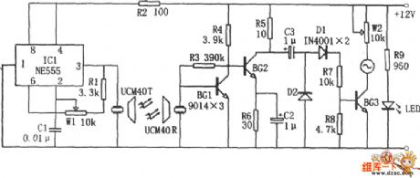
The picture shows the ultrasonic liquid level indicator circuit. This circuit is made up of ultrasonic transmitter circuit and receiver circuit.The ultrasonic transmitter circuit is made up of 555, R1, W1, C1 and ultrasonic transmitter head UCM40T. The ultrasonic receiver circuit is made up of the corresponding receiving head UCM40R, cascade amplifier BG1 and BG2, detecting circuit and so on. When the liquid level is closing to the receiver head, the voltage meter's deflection angle would be increasing. The closer to the liquid level, the bigger the corresponding deflection angle would be.Because the ultrasonic has the featrue that it would not be effected by the liquid's concentration and electric conductivity, so this circuit would be better and have higher accuracy than general contacting liquid level display circuit. (View)
View full Circuit Diagram | Comments | Reading(4784)
CXA-1213S Luminance And Chrominance Signal Processing Integrated Circuit
Published:2011/7/13 22:02:00 Author:Robert | Keyword: Luminance, Chrominance, Signal, Processing, Integrated


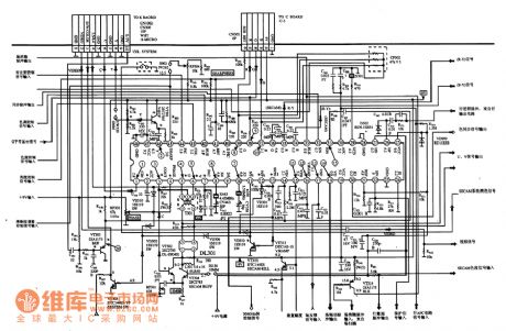
The CXA-1213S is a luminance and chrominance signal processing IC produced by the Sony company which is widely used in sony series large-screen color TV sets.
1.Its functional features.
The CXA-1213S IC has internal color format detection and conversion circuit, chrominance signal decoding circuit and its corresponding auxiliary circuit.
2.Its pin's function and data.
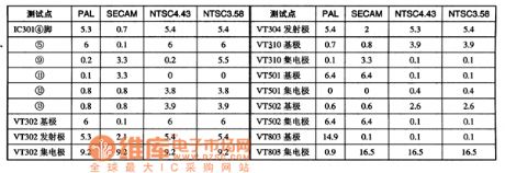
The CXA-1213S IC uses 48-pin dual inline package. Its pin's function and data is listed in table 1. The format conversion circuit key points' voltage is listed in table 2.
The table 1 shows the CXA-1213S IC's pin's function and data.
The table 2 shows the format conversion circuit key points' voltage.
3.Typical application circuit.
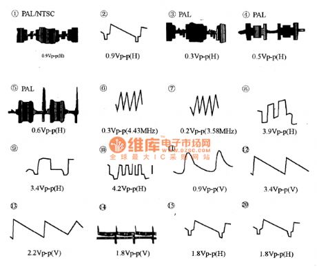
The CXA-1213S IC's typical application circuit is shown in picture 1. The CXA-1213S related pins' waveform is shown in picture 2. (This picture is the original picture of the color TV sets, so the symbols which don't meet the standard have not been modified).
The picture 1 shows the CXA-1213S IC's typical application circuit.
The picture 2 shows the CXA-1213S IC's related pins' signal waveform. (View)
View full Circuit Diagram | Comments | Reading(7727)
Golf Bora Comfort System Circuit
Published:2011/7/15 8:34:00 Author:Robert | Keyword: Golf, Bora, Comfort, System
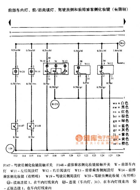
The pictures show the Golf Bora comfort system circuit.
The first picture shows the driver's side door electronic control unit, driver's side door window lifter, car inner lock switch, window lifter switch, rear door window lifter chain switch.
The second picture shows the driver's side door electronic control unit, driver's side central door clock, central door clock indicator lamp, left door warning lamp.
The third picture shows the driver's side door electronic control unit, rearview mirror adjustment switch, car external rearview mirror heating switch, rearview mirror folding switch.
The fourth picture shows the driver's side door electronic control unit, driver's side door electrical adjustable rearview mirror.
The fifth picture shows the front passenger side door electronic control unit, front passenger side door window lister, front passenger side central door lock.
The sixth picture shows the front passenger side door electronic control unit, front passenger side door external rearview mirror (electrical adjustment), right car door warning light.
And so on. (View)
View full Circuit Diagram | Comments | Reading(873)
Qisheng AV-737 Power Amplifier Complicated Troubleshooting Two Examples Circuits
Published:2011/8/2 21:46:00 Author:Robert | Keyword: Qisheng, Power Amplifier, Complicated, Troubleshooting, Two, Examples


Example 1: the error symptom. A Qisheng AV-737 amplifier is combined with VCD. When it connects the signal wire and plug in the power, the amplifier would enter the standby mode. If the user opens the VCD power firstly and thenopens the amplifier, the amplifier's all functions would be disabled (include remote-control function). When it occurs the crash failures, at this time pressing the AV-737's power plug solely, and plugging in after some seconds, then it would start normally. If each time openning the AV-737 power amplifier power and then openning VCD, it would not have the error above.Analysis and maintenance. When it occurs the faults, the standby power supply is tested to be normal, the CPU1997(or 9800)'s pin 64 and pin 46's 5V power is also tested to be normal, the pin 32 and pin 44 (ground port) are normally connected to the ground. Pressing the power switch button, the CPU's pin 28 (power) control output port has no variety. The AV-737's power switch mode is touch-button control switch. When it is connected, the CPU would receive the starting command and its pin 28 would output high voltage level. Then the control the relay to be closed to make the whole device's power connected. (View)
View full Circuit Diagram | Comments | Reading(6047)
Audi A4 1.8T Engine Circuit
Published:2011/8/2 21:57:00 Author:Robert | Keyword: Audi, A4, 1.8T, Engine
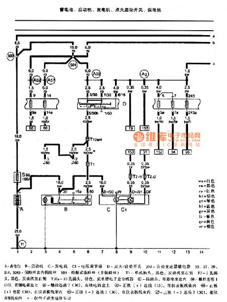


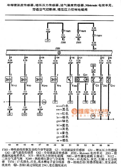

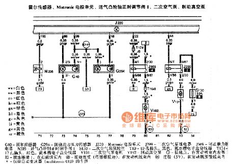

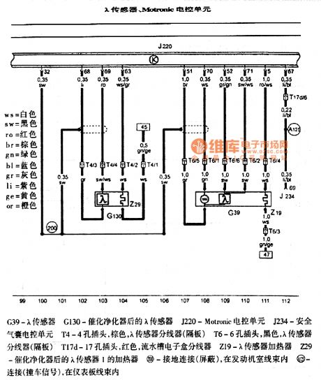
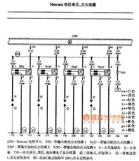
The pictures show the Audi A4 1.8T engine circuits.
The first picture shows the battery, starting machine, generator, ignition starting switch, fuse.The second picture shows the fuel pump relay, Metronic ECU, Motronic power supply relay, fuse.The third picture shows the air flow meter, radiator exit cooling fluid temperature sensor, Motronic ECU, fuel injection pump.The fourth picture shows the cooling fluid temperature sensor, boost pressure sensor, intake air temperature sensor, Motronic ECU, bypass air shut-off valve, boost pressure control solenoid valve.The fifth picture shows the engine speed sensor, knock sensor 1, knock sensor 2, Motronic ECU.The sixth picture shows the hall sensor, Motronic ECU, admission camshaft correct timing adjustment valve 1, secondary air pump, brake vacuum pump.The seventh picture shows the accelerator pedal position sensor, Motronic ECU, throttle ECU.The eighth picture shows the λ sensor, Motronic ECU.The ninth picture shows the Motronic ECU and ignition coil. (View)
View full Circuit Diagram | Comments | Reading(3167)
Instrumentation Amplifier (OP08) Circuit With Differencial Input Pre-Amplifier
Published:2011/8/3 20:26:00 Author:Robert | Keyword: Instrumentation, Amplifier, Differencial, Input, Pre-Amplifier
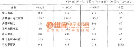
For the instrumentation amplifier of electronic measuring circuit, its input signal's amplitude peak may usually be a few mV. But the common-mode noise voltage level could be as high as a few volts. So the instrumentation amplifier's input drift, noise rejection and common-mode rejection ratio is significant for the amplifier's dynamic performance. At the same time the measured source's internal resistance could not be controlled. And the signal internal resistance's variation could make the amplifier's resistors mismatch, which connect respectively from the two input ports to ground. This mismatch could cause not only the change of the gain, but also cause the common-mode rejection ratio decreasing.
(View)
View full Circuit Diagram | Comments | Reading(686)
Single-Port Input Into Differencial Input Feeder Line Driver (OPA2604 And BUF634) Circuit
Published:2011/8/7 21:58:00 Author:Robert | Keyword: Single-Port, Input, Differencial, Feeder Line, Driver


The picture shows the single-port input into differencial input feeder line driver. The circuit uses 4 different integrated operational amplifiers: high-fidelity dual operational amplifiers OPA2604, which is a FET input type operational amplifier; two 250mA high-speed buffer BUF634, which is working in wide-band mode (the pin 1 should be connected to the negative power port which is pin 4), that means its band width is extended to about 180MHz, and in this case the BUF634's voltage magnification is 1; also a INA103 operational amplifier, which is a instrument amplifier with low noise and low distortion. If necessary, it could also use the INA101 to replace the INA103.
The integrated dual operational amplifiers OPA2604's main parameters (typical value) are shown in the picture 2. (View)
View full Circuit Diagram | Comments | Reading(1186)
μPC2002 9W Audio Power Amplifier Circuit
Published:2011/7/18 9:27:00 Author:Robert | Keyword: 9W, Audio, Power, Amplifier

The μPC2002 is a audio power amplification IC which uses 5-pin single inline plastic package. It can be divided to H type and V type according to the shape of its lead wire. This circuit has a large output power and low distortion and low noise. It also has the low impact sound when starting.The circuithasprotection circuits for power surge, over voltage and load's short circuit and so on. So it is widely used in car stereo radio and used as audio power amplifier in videocorder. Its typical application circuit is shown in the picture. (View)
View full Circuit Diagram | Comments | Reading(1953)
Logic Signal Long Time Delay Circuit
Published:2011/8/2 21:49:00 Author:Robert | Keyword: Logic, Signal, Long, Time Delay
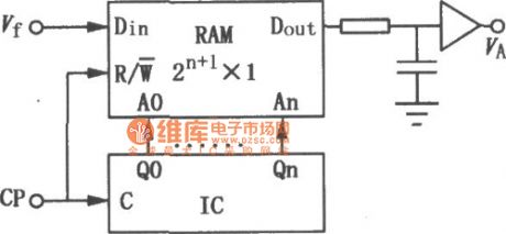
If you want to make the serial input logic signal Vtoutputafter thedelay time, it could use the circuit shown in the picture. This circuit uses a RAM and a binary counter. They could both use a same clock signal CP. In the first half cycle of the clock signal, the counter's data would add 1 which would output as the address for reading data. In the next half cycle of the clock signal the new input data Vf would be writen to the same unit. This signal could be read after the time of td=2n+1Tcp. Here Tcp is the cycle time of the clock signal. (View)
View full Circuit Diagram | Comments | Reading(1261)
50W Hi-Fi Audio Integrated Power Amplifier Circuit Composed Of TDA1514A
Published:2011/7/17 22:09:00 Author:Robert | Keyword: 50W, Hi-Fi, Audio, Integrated, Power Amplifier
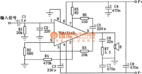
The picture shows the audio integrated power amplifier. It's the typical application circuit composed of TDA1514A. TDA1514A is a 50W Hi-Fi audio amplification IC produced by the Philips company. Its internal protection circuitsare complete which means it has not only the general over-heating, output short circuit protection, but also the safe operating area protection. The circuit is also set up a silent switch to suppress the starting noise' appearance. In the circuit's design it is also considered the better ripple rejection and low offset with low thermal resistance. (View)
View full Circuit Diagram | Comments | Reading(3018)
| Pages:577/2234 At 20561562563564565566567568569570571572573574575576577578579580Under 20 |
Circuit Categories
power supply circuit
Amplifier Circuit
Basic Circuit
LED and Light Circuit
Sensor Circuit
Signal Processing
Electrical Equipment Circuit
Control Circuit
Remote Control Circuit
A/D-D/A Converter Circuit
Audio Circuit
Measuring and Test Circuit
Communication Circuit
Computer-Related Circuit
555 Circuit
Automotive Circuit
Repairing Circuit