Other Circuit
Logic Signal Long Time Delay Circuit
Published:2011/8/2 21:49:00 Author:Robert | Keyword: Logic, Signal, Long, Time Delay | From:SeekIC

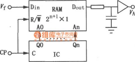
If you want to make the serial input logic signal Vtoutputafter thedelay time, it could use the circuit shown in the picture. This circuit uses a RAM and a binary counter. They could both use a same clock signal CP. In the first half cycle of the clock signal, the counter's data would add 1 which would output as the address for reading data. In the next half cycle of the clock signal the new input data Vf would be writen to the same unit. This signal could be read after the time of td=2n+1Tcp. Here Tcp is the cycle time of the clock signal.
Reprinted Url Of This Article:
http://www.seekic.com/circuit_diagram/Electrical_Equipment_Circuit/Other_circuit/Logic_Signal_Long_Time_Delay_Circuit.html
Print this Page | Comments | Reading(3)

Article Categories
power supply circuit
Amplifier Circuit
Basic Circuit
LED and Light Circuit
Sensor Circuit
Signal Processing
Electrical Equipment Circuit
Control Circuit
Remote Control Circuit
A/D-D/A Converter Circuit
Audio Circuit
Measuring and Test Circuit
Communication Circuit
Computer-Related Circuit
555 Circuit
Automotive Circuit
Repairing Circuit
Code: