
Circuit Diagram
Index 560
The dark room timer circuit
Published:2011/8/15 22:24:00 Author: | Keyword: dark room timer

The 555 is the timing circuit, the timer has 12 basic marks, each interval is half-gear. The switch S1, resistors R1-R12 and capacitors C1 and C2 compose the timing component, the adjusting gear can be divided into 1/4 by C2, i.e when S2 is closed, the exposing time is reduced to 1/4 gear. The switch S3 controls the starting of the timer. When the switch is closed, the 3-pin of IC1 is turned into a high LEV, the solid relay IC2 is conducting, the bulb in the shadow amplifier is lighted.
(View)
View full Circuit Diagram | Comments | Reading(1431)
LM2931 Basic Application Circuit
Published:2011/8/13 8:52:00 Author:Robert | Keyword: Basic, Application

The voltage-adjustable LM2931 is a five-port voltage regulator. It adds the adjustment port (Adj) and on/off port. Its output voltage Uo is set by the resistor R1 and R2 which are connected to the Adj port. The LM2931 basic application circuit is shown in the picture. In the circuit internal part it should control the voltage between Uo-Adj ports to be the same to its internal referenced voltage Uref. (View)
View full Circuit Diagram | Comments | Reading(2199)
The flashlight drive circuit
Published:2011/8/18 7:57:00 Author: | Keyword: flashlight drive
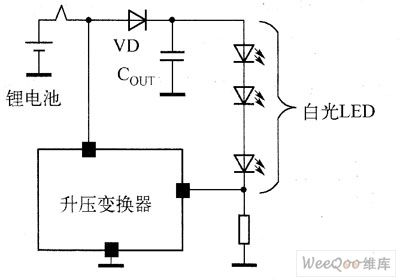

The electric charge is fixed with capacitors as the storage elements, and it doesn't need any external inductors, so the electromagnetic disturbance problem doesn't exist. Besides, the whole resolution takes little PCB coverage, but the efficiency is low. As the flashlight working time is short, which is about 100~300ms, so its efficiency has little effect on the battery lifespan. In figure 2 is the application circuit of the electric charge pump standard white light LED.
Figure 1 the application circuit of the inductance boost transformer drive standard white light LED
(View)
View full Circuit Diagram | Comments | Reading(780)
Three-Port Voltage Regulator Basic Application Circuit
Published:2011/8/18 6:56:00 Author: | Keyword: Three, Port, Regulator, Basic, Application
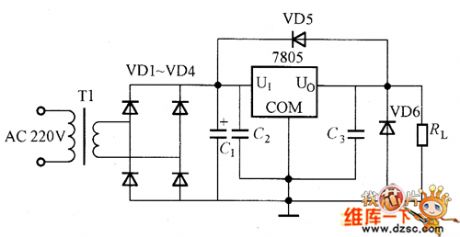
The picture shows the three-port voltage regulator basic application circuit (for example of 7805). The input AC 220V voltage would be through the transformer T1 for voltage buck and the VD1~VD4 bridge rectifier and smoothing capacitance C. After filtering it would get a very stable DC 8~12V voltage and add it to the 7805's input port. For making the circuit stably work, it is connected the capacitace C2, C1 and C3 at the input port and output port. The C2 is the input stability capacitance. When the regulator input impedance is reduced, for avoiding the oscillation, it could use the 0.1uF~1uF ceramic or tantalum capacitors. The C1 is the smoothing capacitance. If it is closing to the 7805, the capacitor C1 can be removed. (View)
View full Circuit Diagram | Comments | Reading(1149)
Three-Port Voltage Regulator Internal Equivalent Circuit
Published:2011/8/14 6:15:00 Author:Robert | Keyword: Three-Port, Voltage, Regulator, Internal, Equivalent

The three-port voltage regulator's three ports are input port U1, output port Uo and common port COM which is usually connecting to the ground. Its internal equivalent circuit is shown in the picture. It is made up by the adjustable tube, protection circuit, control circuit, error amplifier and so on. The voltage between Uo and COM port is comparing with the referenced voltage Uref. They are usually keeping same when working. And when the input voltage UI or output curent Io have variation, they would keep the output voltage Uo stable. (View)
View full Circuit Diagram | Comments | Reading(1006)
Regulator Power Circuit With Output Of 6V/5A
Published:2011/8/14 6:32:00 Author:Robert | Keyword: Power, Regulator, Output
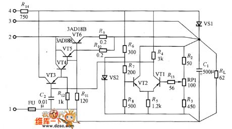
The picture shows the regulator power with output of 6V/5A. The adjustable tube is made up of VT3, VT4, VT5 and VT6. The VT5 and VT6 are in parallel to increase the output current. The R9 and R10 are current equalization resistors to reduce the effects of the differences of tube features and the ICBO. Generally the voltage drop on the resistor is 0.1~1V. (View)
View full Circuit Diagram | Comments | Reading(1245)
Regulator Power Circuit Which Using Transistor As Amplifier
Published:2011/8/13 9:09:00 Author:Robert | Keyword: Regulator, Power, Transistor, Amplifier

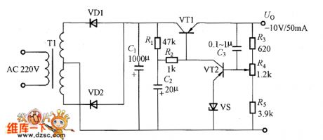
The picture shows the simple and practical regulator power with output voltage of -10V and output current of 50mA. The C2 is coupling capacitor. It makes the output port's ripple directly couple to the amplifier tube VT2's base electrode and it would not be through the sampling resistor. So the output voltage's ripple is very small. The C3 is selected between 0.1uF to 1uF. (View)
View full Circuit Diagram | Comments | Reading(957)
Simple Transistor Regulator Power Circuit
Published:2011/8/14 6:42:00 Author:Robert | Keyword: Simple, Transistor, Regulator, Power
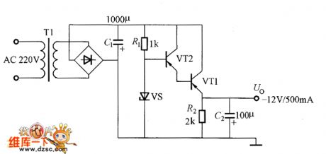
The picture shows the simple transistor regulator power circuit with output voltage of -12V and output current of 500mA. The adjustable tube VT1 and VT2 use the Darlington connecting method to improve the adjustment sensitivity. The C2's function is to further reduce the probable ripple. This circuit's output voltage is closing to the zener diode VS's reverse breakdown voltage, so it can't be adjusted. It is suitable for the cases which need large current and not very high stability. (View)
View full Circuit Diagram | Comments | Reading(1483)
Basic Voltage Regulator Composed Of Zener Diode
Published:2011/8/14 8:21:00 Author:Robert | Keyword: Basic, Voltage, Regulator, Zener Diode
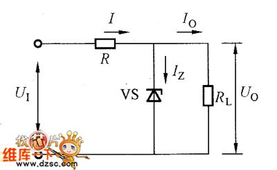
The picture shows the basic voltage regulator composed of zener diode. In the circuit, the R is current-limiting resistor. The RL is loading resistor. The VS is zener diode which is used as the adjustable element. It should note the connecting method when using, which is that it should be reversely connected to the circuit. The circuit regulator process is simply introduced here: when the U1 is increasing to cause the Uo to be bigger, the VS's current Iz is increasing, so the voltage drop on the R is increasing. Thus it keeps the stability of Uo. The same, when the U1 reduces to cause the Uo to reduce, the Iz is also reduced. Then the voltage drop on R is reduced to keep the stability of Uo.
The picture shows the basic voltage regulator composed of zener diode. (View)
View full Circuit Diagram | Comments | Reading(2280)
Mazda 96 PROBE ABS Circuit
Published:2011/8/11 7:50:00 Author:Robert | Keyword: Mazda, PROBE, ABS

The Mazda 96 PROBE ABS circuit is shown in the picture. (View)
View full Circuit Diagram | Comments | Reading(505)
Mazda 96 PROBE Electric Seat Circuit
Published:2011/8/11 7:53:00 Author:Robert | Keyword: Mazda, PROBE, Electric, Seat
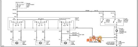
The Mazda 96 PROBE electric seat circuit is shown in the picture. (View)
View full Circuit Diagram | Comments | Reading(559)
Mazda 96 PROBE Door Lock Circuit
Published:2011/8/11 7:55:00 Author:Robert | Keyword: Mazda, PROBE, Door, Lock
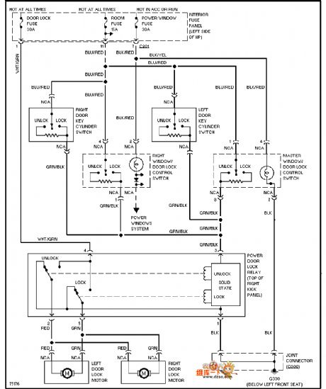
The Mazda 96 PROBE door lock circuit is shown in the picture. (View)
View full Circuit Diagram | Comments | Reading(535)
Mazda 96 PROBE Car Internal Light Circuit
Published:2011/8/11 8:26:00 Author:Robert | Keyword: Mazda, PROBE, Car, Internal, Light

The Mazda 96 PROBE car internal light circuit is shown in the picture. (View)
View full Circuit Diagram | Comments | Reading(527)
Mazda 96 PROBE Shift Gear Interlocking Circuit
Published:2011/8/11 8:30:00 Author:Robert | Keyword: Mazda, PROBE, Shift Gear, Interlocking

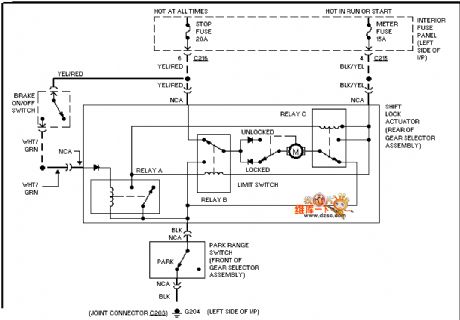
The Mazda 96 PROBE shift gear interlocking circuit is shown in the picture. (View)
View full Circuit Diagram | Comments | Reading(761)
Mazda 96 PROBE (2.0L) Engine Performance Circuit
Published:2011/8/11 8:33:00 Author:Robert | Keyword: Mazda, PROBE, 2.0L, Engine, Performance
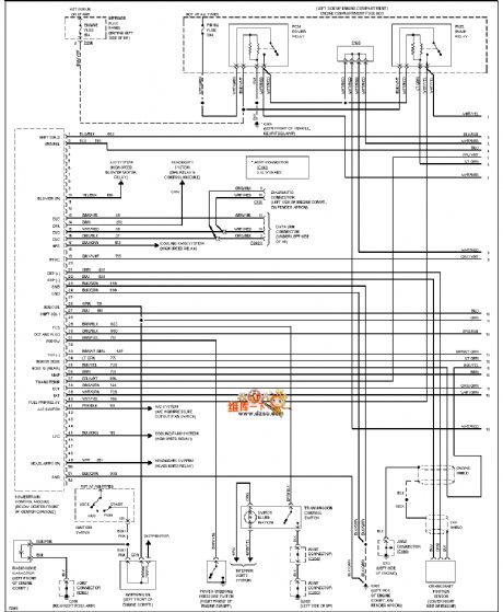
The Mazda 96 PROBE (2.0L) engine performance circuit is shown in the picture. (View)
View full Circuit Diagram | Comments | Reading(580)
Capacitance Input Type Rectifier Circuit
Published:2011/8/14 1:54:00 Author:Robert | Keyword: Capacitance, Input, , Rectifier

The capacitance input type rectifier circuit has the single-phase half-wave rectifier circuit, single-phase middle-tap full-wave rectifier circuit, single-phase bridge rectifier circuit and voltage doubler rectifier circuit and so on. The picture (a) shows the single-phase half-wave rectifier circuit. The circuit is simple, but its output current is small and ripple is big. The picture (b) shows the single-phase middle-tap full-wave rectifier circuit. It is suitable for medium and small power supply circuits. The picture (c) shows the bridge rectifier circuit. It has more two diodes than the middle-tap rectifier circuit. But its transformer power is just 0.7 times of the middle-tap rectifier circuit. (View)
View full Circuit Diagram | Comments | Reading(2336)
LT1773 Application Circuit
Published:2011/8/11 6:41:00 Author:Robert | Keyword: Application
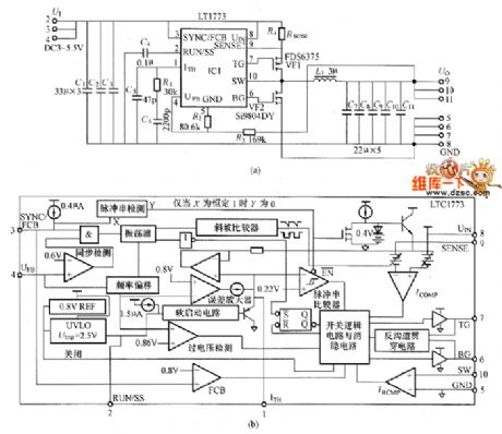
The LT1773 application circuit is shown in the picture. (View)
View full Circuit Diagram | Comments | Reading(1013)
TL1681/LTC1698 Application Circuit
Published:2011/8/11 6:39:00 Author:Robert | Keyword: Application

The TL1681/LTC1698 application circuit is shown in the picture. (View)
View full Circuit Diagram | Comments | Reading(846)
Flyback Type Converter Circuit Composed Of MAX5021
Published:2011/8/14 3:39:00 Author:Robert | Keyword: Flyback, Converter
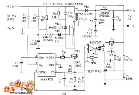
The picture shows the flyback type convertor composed of MAX5021. The MAX5021 is a isolated power PWM current-type integrated controller with wide input voltage range. It is suitable for the remote communication. This controller works under the 262kHz fixed oscillation frequency switching and it could reduce the noise efficiently. It has a big hysteresis feature and low starting current. It also has the low-voltage closing and locking function and so on. If MAX5021 is used in the power supply with wide voltage input range and low output power, it could reduce the power supply's power consumption.
The picture shows the flyback type converter circuit composed of MAX5021. (View)
View full Circuit Diagram | Comments | Reading(1880)
Low Noise Convertor Circuit Composed Of LT1777
Published:2011/8/13 22:19:00 Author:Robert | Keyword: Low, Noise, Convertor
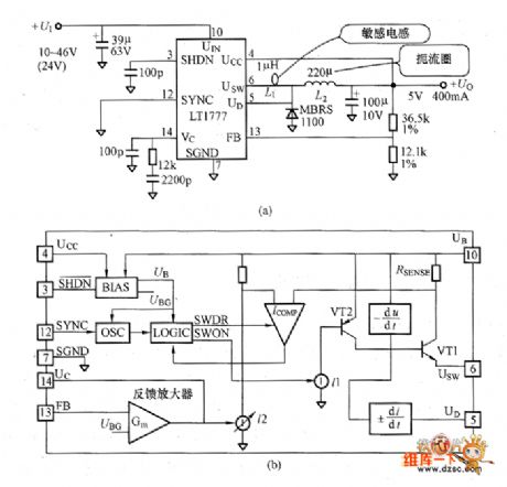
The picture shows the convertor circuit composed of LT1777. This is a low noise non-isolated buck type DC-DC convertor with output of 5V/400mA. The LT1777 has internal di/dr and dta/dr limiting circuit, switching circuit with rated current peak value of 700mA, current control mode short-circuit protection circuit. Its oscillation frequency is 100kHz. The picture (c) shows the efficiency features at input voltage of 12V, 24V, 36V. These are the tested efficiency under the inductor L1 of 0uH, 1uH, 2.2uH. If connecting the sensing inductor it could reduce the noise. But from the efficiency feature curve we know that the internal power consumption would increase and the efficiency would be lower. So it should note this problem when selecting the sensing inductor. (View)
View full Circuit Diagram | Comments | Reading(865)
| Pages:560/2234 At 20541542543544545546547548549550551552553554555556557558559560Under 20 |
Circuit Categories
power supply circuit
Amplifier Circuit
Basic Circuit
LED and Light Circuit
Sensor Circuit
Signal Processing
Electrical Equipment Circuit
Control Circuit
Remote Control Circuit
A/D-D/A Converter Circuit
Audio Circuit
Measuring and Test Circuit
Communication Circuit
Computer-Related Circuit
555 Circuit
Automotive Circuit
Repairing Circuit