
Circuit Diagram
Index 549
LC40159 white LED driver circuit diagram
Published:2011/8/12 1:13:00 Author:Lucas | Keyword: white LED driver
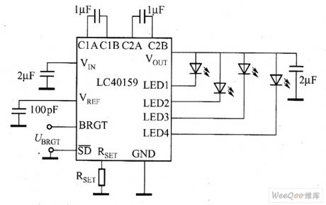
VIN side in the figure shows the input voltage of the power supply, and input voltage range is 2.7 ~ 5.5V; VREF side is the internal reference voltage, SD side is the enable signal input end, when it is input H signal, LED begins to glow; when it is input L signal, LED turns off. RSET side have set the peripheral resistor which can generate a constant current. VOUT terminal is the output end of the boost circuit, and it is connected with white LED cathode, because the converter output voltage VOUT can be synchronized with the oscillator circuit fluctuates, the VOUT terminal can be connected output capacitor in parallel to suppress fluctuations of the output voltage.
(View)
View full Circuit Diagram | Comments | Reading(824)
SP7616/SP7615 LED driver circuit diagram
Published:2011/8/12 2:14:00 Author:Lucas | Keyword: LED driver
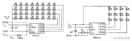
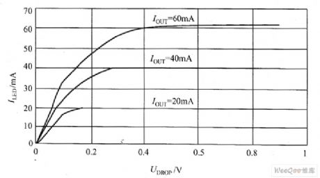
SP7616 is the 4-channel constant-current linear white LED driver with operating voltage in 4.5 ~ 30V, and each channel supports the maximum of ω irregular current. SP7616 contains current-matching circuit, which allows the current difference between each channel to be less than 1.5%. SP7616/SP7615's typical application circuit is shown in Figure 1, each channel of SP7616 supports 60mA current and SP7615 supports 126mA current. In the SP7616 typical application circuit shown in Figure (a), if DIN (N × UF + UDROP), then the current flowing through the 4-channel white LED is constant and matched.
(View)
View full Circuit Diagram | Comments | Reading(1603)
LM3354/LM2792 white LED driver circuit diagram
Published:2011/8/12 2:22:00 Author:Lucas | Keyword: white LED driver
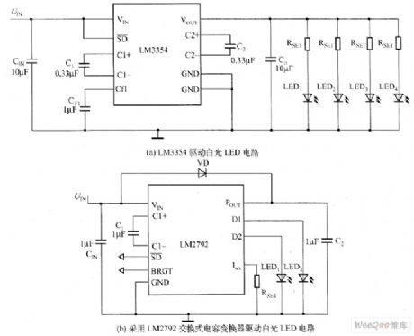
Charge pump white LED driver circuit is shown as the chart. Figure 1 (a) is the LM3354 charge pump white LED driver circuit with voltage regulation output function, and it can output 4.1V stable voltage. LM3354 charge pump input voltage range is 2.5 ~ 5.5V, and the output voltage range can be chosen from nominal values. LM3354 is used as white LED driver, which can select 4.1V output voltage. LM3354 charge pump switching frequency is 1MHz, so you can use smaller-capacity switch capacitor; the maximum output current is 90mA, and it contains on-chip thermal protection circuit with quiescent current in 475μA, and the current is 5μA when the circuit is off.
(View)
View full Circuit Diagram | Comments | Reading(1203)
CAT3200/CAT3200-5 white LED driver circuit diagram
Published:2011/8/12 2:36:00 Author:Lucas | Keyword: white LED driver
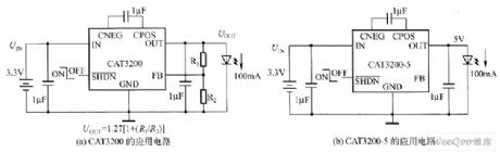
CAT3200 and CAT3200-5 are the switched-capacitor boost converter, which can output low-noise adjustable voltage. CAT3200-5's fixed output voltage is 5V. CAT3200 can use an external resistor to make the output voltage be adjustable. Their frequency is fixed at 2MHz 1μF, and the charge pump allows to use small ceramic capacitors, and wide input supply voltage range (2.7 ~ 4.5V) supports the maximum 100mA output load that allows the device ideal for battery-powered electronic device. Their shutdown control input allows the device to enter power-down mode, which allows the supply current to be less than 1μA.
(View)
View full Circuit Diagram | Comments | Reading(758)
CAT3604 white LED driver circuit diagram
Published:2011/8/12 2:41:00 Author:Lucas | Keyword: white LED driver
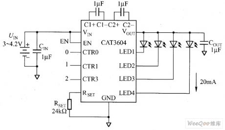
CAT3604 is the charge pump which works in 1x, 1.5x mode, and adjusting the current of each white LED pin (it has total four white LED pins) can regulate the brightness uniformity. CAT3604 work in a fixed frequency of 1MHz, it uses low-value ceramic capacitors. The enable input pin can make CAT3604 enter the power-down mode with input quiescent current which almost zero . CAT3604 can drive parallel white LEDs to provide tightly matched regulated current. The external resistor RSET controls the output current. CAT3604 is suitable for single-cell lithium-ion battery-powered portable electronic devices.
(View)
View full Circuit Diagram | Comments | Reading(772)
MAX1561/MAX1599 white LED driver circuit diagram
Published:2011/8/12 3:05:00 Author:Lucas | Keyword: white LED driver
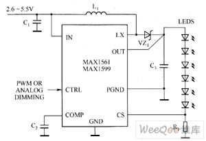
MAX1561/MAX1599 contains high-voltage, low RDS-ON N-channel MOSFET switch, which provides high conversion efficiency and extends battery life. Dual-mode input provides a simple brightness adjustment and switching control. MAX1561's 1MHz (MAX1599 to 500kHz) high-speed, current-mode pulse-width modulation (PWM) architecture allows for small input and output capacitors and inductors, and to minimize the ripple on input power (battery). Programmable soft-start function can eliminate inrush current during startup.
(View)
View full Circuit Diagram | Comments | Reading(1259)
MAX1578/MAX1579 white LED driver circuit diagram
Published:2011/8/11 4:22:00 Author:Lucas | Keyword: white LED driver
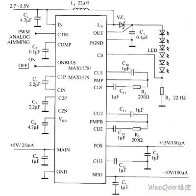
MAX1578/MAX1579 offer 4-way adjustable output, which can provide voltage for small active-matrix TFT-LCD display in portable electronic devices, and each device contains three charge pumps for LCD bias power and a boost converter, this converter can drive eight white LEDs for the backlight configuration. MAX1578/MAX1579 input voltage range is 2.7 ~ 5.5V. MAX1578 can adjust constant white LED current in the whole temperature range. MAX1579 has a cooling function to avoid to drive white LEDs in too high temperature environment.
(View)
View full Circuit Diagram | Comments | Reading(1224)
MAX1582/MAX1582Y white LED driver circuit diagram
Published:2011/8/11 3:35:00 Author:Lucas | Keyword: white LED driver

MAX1582/MAX1582Y are the boost converter white LED drivers with dual output and high efficiency, and they are widely used to drive the primary and secondary screen white LED backlight display in mobile phones, and the power consumption is reduced by 25%. MAX1582/MAX1582Y can drive six series of white LEDs by constant current, thus they can provide dual display (primary and second) backlight driver for mobile phones and other portable electronic devices, and they do not need to configure the current limiting resistors. Its proprietary dual-output, step-up pulse-width modulation (PWM) converter is built-in 30V, low RDS-ON, N-channel MOSFET switch, which can improve efficiency and extend battery life.
(View)
View full Circuit Diagram | Comments | Reading(549)
MAX1583 white LED driver circuit diagram
Published:2011/8/11 3:41:00 Author:Lucas | Keyword: white LED driver
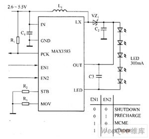
MAX1583 boost converter can drive five white LEDs by constant current, and it provides camera flash driver for mobile phone, PDA, DSC, and other portable electronic devices. MAX1583 includes a 24V boost converter and a high-voltage LD0 current regulator to achieve high efficiency and extend battery life. Its two logic inputs can be used to select the following four modes: shutdown mode, high efficiency, continuous flash movie mode, precharge mode, flash mode. MAX1583 uses the 10-pin 3mm × 3mm TDFN package (the maximum height is 0.8mm).
(View)
View full Circuit Diagram | Comments | Reading(1096)
MAX1553/MAX1554 white LED driver circuit diagram
Published:2011/8/11 4:13:00 Author:Lucas | Keyword: white LED driver
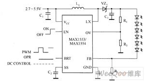
MAX1553/MAX1554 can drive white LEDs in constant current, so it can provide high-efficiency backlight for mobile phone, PDA and other portable electronic devices. MAX1553/MAX1554 contains 40V, low RDS-ON, N-channel M0SFET switch, which greatly improves the conversion efficiency and extends battery life. MAX1553 can drive 2 to 6 white LEDs to provide 480mA current limiting; the MAX1554 can drive 10 white LEDs to provides 970mA current limiting. MAX1553/MAX1554 IC provides two simple brightness adjustment methods of single analog and PWM.
(View)
View full Circuit Diagram | Comments | Reading(887)
MAX16803 white LED driver circuit diagram
Published:2011/8/11 3:51:00 Author:Lucas | Keyword: white LED driver
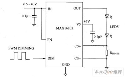
MAX16803 current regulator's input voltage range is 6.5 ~ 40V, which can provide 350mA total current for driving one or more strings of high brightness white LEDs. MAX16803 output current value can be set by an external galvanometer resistor connecting with white LED in series. It allows a wide range of PWM to adjust brightness by brightness control input terminal, and the wave shaping circuit reduces EMI, the differential current detection improves noise immunity. MAX16803 is ideal for high-voltage input applications, the built-in regulator can reduce external components' number and provide ± 3.5% output current accuracy.
(View)
View full Circuit Diagram | Comments | Reading(956)
EL7516 white LED driver circuit diagram
Published:2011/8/11 4:03:00 Author:Lucas | Keyword: white LED driver
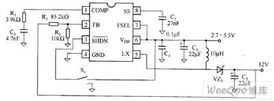
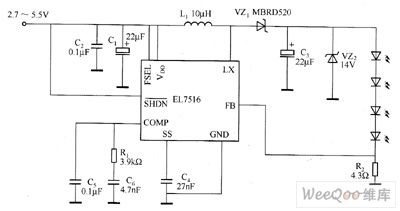
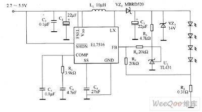
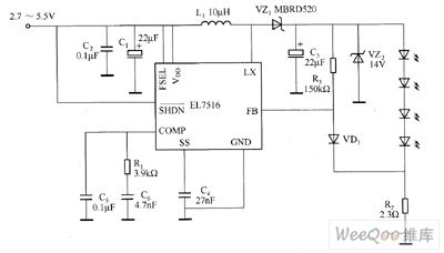
EL7516 is a typical step-up chip, which works at 1.2MHz fixed-frequency PWM mode, and it contains an 1.5A, 200mΩ MOSFET. Figure 1 shows the typical application circuit of EL7516. The DC / DC boost effect can change the 2.7 ~ 5.5V input voltage into 12V constant output voltage. It is similar to the general PWM control chip, the FB-pin sets the output voltage by the value of R1, R2 resistors. It is easy to change EL7516's constant pressure lines to constant current lines by driving white LED. Standard LED driver diagram is shown in Figure 2, as long as to change R2 in Figure 2, the white LED current is adjusted.
(View)
View full Circuit Diagram | Comments | Reading(1137)
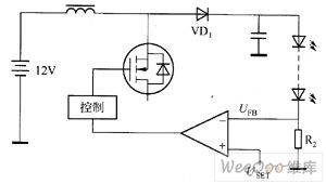
XC9103 white LED driver circuit diagram
Published:2011/8/11 3:27:00 Author:Lucas | Keyword: white LED driver


Figure 1 is the commonly series white LED driver circuit schematic, and the driver IC in the figure is the XC9103 Series DC / DC converter. When it uses XC9103 Series devices, it can use the ceramic capacitor as the output capacitor CL to suppress unwanted signal radiation. In Figure 1, the step-up DC / DC converter outputs white LED drive current, of which value is equal to the value from FB pin control voltage dividing the resistance of the connecting resistor. XC9103's FB-pin control voltage is 0.9V, XC6367's FB-pin control voltage is 1.0V. Therefore, changing the resistance can adjust white LED drive current to the desired value.
(View)
View full Circuit Diagram | Comments | Reading(759)
MAX16823 White LED driver circuit diagram
Published:2011/8/16 20:41:00 Author: | Keyword: White LED driver

MAX16823's main technical characteristics are as follow. ① 5.5 ~ 40V operating voltage range. ② adjustable constant output current (5 ~ 70mA, it uses external BJT to reach 2A). ③ ± 5% output current accuracy. ④ white LED open detection. ⑤ 3 separate high-pressure DIM inputs. ⑥ Built-in 3-channel, low dropout (maximum value is 0.7V) and adjusting components. ⑦ undervoltage lockout function(output short-circuit protection and thermal shutdown). ⑧it contains 3.4V regulator to provide 4mA current. ⑨ low 203mV precision current-sense reference.
(View)
View full Circuit Diagram | Comments | Reading(1294)
MAX16818 White LED driver circuit diagram
Published:2011/8/16 20:45:00 Author: | Keyword: White LED driver

MAX16818's main technical characteristics are as follow. ① high-current white LED driver controller IC, the output current is up to 30A. ② it uses average current mode control, true differential remote sensing input technology. ③ programmable switching frequency is synchronized by an external controller in the 125kHz ~ 1.5MHz range. ④ 4.75 ~ 5.5V or 7 ~ 28V input voltage range. ⑤ it contains a 4A gate driver. ⑥ clock output is used for 180 ° out of phase work. ⑦ it has output overvoltage protection and hiccup mode over-current protection and thermal shutdown protection.
(View)
View full Circuit Diagram | Comments | Reading(1245)
Actin voltage amplifier circuit diagram
Published:2011/8/12 3:20:00 Author:Lucas | Keyword: Actin voltage amplifier
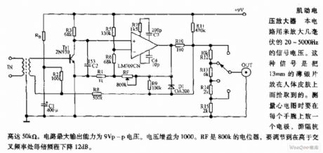
This circuit is used to enlarge a few millivolts of 20 ~ 5000HZ signal voltage. This signal is picked up by putting the 13mm thin silver film on human skin. When people do ECG measurements, each wrist should be put one electrode, the source impedance is up to 50kΩ. The maximum output capacity of the circuit is 9Vp-p voltage. The voltage gain is 1000. RF is the 800K potentiometer to adjust the frequency be higher crossover frequency, then the octave is shut down 12dB.
(View)
View full Circuit Diagram | Comments | Reading(1402)
Teana A33-EL electric door lock circuit diagram 3
Published:2011/8/12 3:24:00 Author:Lucas | Keyword: Teana, electric door lock

View full Circuit Diagram | Comments | Reading(826)
Teana A33-EL electric door lock circuit diagram 2
Published:2011/8/12 3:24:00 Author:Lucas | Keyword: Teana , electric door lock

View full Circuit Diagram | Comments | Reading(966)
Teana A33-EL electric door lock circuit diagram 1
Published:2011/8/12 3:25:00 Author:Lucas | Keyword: Teana , electric door lock
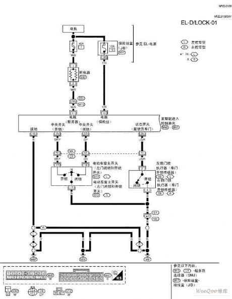
View full Circuit Diagram | Comments | Reading(993)
Electronic ballast circuit diagram
Published:2011/8/12 3:22:00 Author:Lucas | Keyword: Electronic ballast
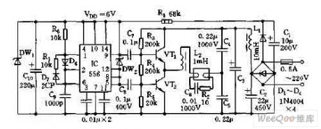
View full Circuit Diagram | Comments | Reading(1349)
| Pages:549/2234 At 20541542543544545546547548549550551552553554555556557558559560Under 20 |
Circuit Categories
power supply circuit
Amplifier Circuit
Basic Circuit
LED and Light Circuit
Sensor Circuit
Signal Processing
Electrical Equipment Circuit
Control Circuit
Remote Control Circuit
A/D-D/A Converter Circuit
Audio Circuit
Measuring and Test Circuit
Communication Circuit
Computer-Related Circuit
555 Circuit
Automotive Circuit
Repairing Circuit