
Circuit Diagram
Index 552
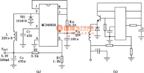
MC3406A buck DC-DC convertor
Published:2011/8/11 11:17:00 Author:leo | Keyword: Buck, DC-DC convertor
View full Circuit Diagram | Comments | Reading(1243)
The triangular wave generator made by CD4046
Published:2011/8/17 20:41:00 Author: | Keyword: Triangular wave, generator

As the picture shows, this circuit can use to generate the triangular wave with fixed amplitude and based on earth potential. Its frequency can follow the frequency of PLL input signal. (View)
View full Circuit Diagram | Comments | Reading(1846)
The switch power resource circuit formed be three-port PWM switch power supply IC
Published:2011/8/6 22:01:00 Author:leo | Keyword: Switch power resource circuit, three-port PWM switch power supply IC

TOP2XX series IC is a kind of three ports switch power supply chip which integrates control circuit and power switch. Its package is TO-220 whose pin names and functions are shown in the picture (a).There are oscillator, PWM comparator, difference amplifier, logic circuit and MOSFET output switch tune and over voltage/over current protection circuit. Picture(b)is the classic applying circuit of TOP204. The features of this power resource are as the followings: Input current is 85 V to 265 V AC; output voltage is 15V±2%; output power is 30 W. (View)
View full Circuit Diagram | Comments | Reading(1831)
Switch constant current power supply appliying circuit made by W723
Published:2011/8/10 23:29:00 Author:leo | Keyword: Switch, power supply, constant current

>
As the picture shows, it is a fixed current switch regulator applying circuit which is formed by W723. W723 is a multi-port adjustable positive integrated regulator. Its base voltage is about 7.2 V, which passes through R1 and R2 to add the 3V voltage to the input ports of the same phase. At the same time, the base voltage also passes through R3 and R4 to add the voltage to input ports of the negative phase. When the positive and negative phase input ports are balanced, voltage of R5 is about 1 V. (View)
View full Circuit Diagram | Comments | Reading(728)
The adaptive and adjustable regulated power supply made by LM317
Published:2011/8/6 22:40:00 Author:leo | Keyword: Adaptive circuit, adjustable circuit, regulated power supply

The picture shows a adaptive and adjustable regulated power supply. This power supply uses LM317 as the regulated component. Using this circuit to adjust the input voltage based on the output voltage which can reduce the voltage difference between input and output voltage to lower the power consumption of the power supply. VT2, VD5, VW, R5, R6, C10 and K form adaptive converting circuit. When the output voltage is lower than 14 V, VW, VT2 and K all stop and the 14 V voltage of transformer is connected to regulated circuit. Appositively, when output voltage is over 14 V, VM, VT2 and K are all working well, the transformer offers 28 V AC voltage to regulated circuit.
(View)
View full Circuit Diagram | Comments | Reading(2413)
Photonics relay with locking function which is made by Darlington phototransistor
Published:2011/8/11 11:06:00 Author:leo | Keyword: Photonics relay, locking function, Darlington phototransistor

View full Circuit Diagram | Comments | Reading(651)
The oscillator formed by CC4066
Published:2011/8/14 5:48:00 Author:leo | Keyword: Oscillator

As the picture shows, this is an oscillator made by CMOS analog electronic switch CC4066. The circuit in the picture is formed by two electronic switches. The frequency of this oscillator is decided by resistance components. When the R1 =R2 and C1=C2, the circuit generates square wave and f=1/2RC. (View)
View full Circuit Diagram | Comments | Reading(1679)
Key oscillator made by CC4528
Published:2011/8/14 7:00:00 Author:leo | Keyword: Key oscillator

View full Circuit Diagram | Comments | Reading(547)
Square wave oscillator(741)
Published:2011/8/14 7:06:00 Author:leo | Keyword: Square wave, oscillator

As the picture shows, this is an oscillator of square wave. It can generate the square wave with more than 100 to 1000 Hz frequency. Its frequency can be adjusted through resistor with 100kohms and 1Mohms. And the linearity of its output square wave is adjusted by resistor with 10kohms. If it only outputs at the same frequency, it can use fixed resistor to replace 100kohms and 1Mohms resistors. (View)
View full Circuit Diagram | Comments | Reading(1913)
The frequency divider circuit with a rate of 18 and made by CD4017
Published:2011/8/14 7:10:00 Author:leo | Keyword: Frequency divider, rate

View full Circuit Diagram | Comments | Reading(2156)
AC-DC three-digit voltmeter circuit
Published:2011/8/11 4:36:00 Author:John | Keyword: three-digit voltmeter

The voltmeter circuit’s input stage uses operational and a diode feedback to form a linear peak rectifier circuit. Then the circuit is isolated via R2/R3 divider and is sent to A / D converter CA3162E output from the dual integral multiple BCD. It can be also said to that the 0 ~ 1V DC test voltage is directly added between the differential inputs ⑾ and ⑽ of the CA3162E. If ⑽ is not connected to ⑺ for use, resistor with less than100kΩ should be used to connect to them. The voltmeter input ranges from 0 to +9.99 V. It only displays the peak value of the AC input voltage. When AC rms should be displayed, the transform circuit is needed to attenuate appropriately.
(View)
View full Circuit Diagram | Comments | Reading(1975)
Linear output integrated magnetic field sensor temperature compensation circuit
Published:2011/8/11 5:12:00 Author:John | Keyword: Linear output, integrated magnetic field sensor, temperature compensation


Constituted by the AD22151 bipolar mode temperature compensation circuit is as shown.
The circuit has the following characteristics: ① The temperature compensation resistor R1 is connected between the TC2 side and TC3 side; ② Zero magnetic field is biased on the UCC / 2; ③ It is able to compensate low temperature coefficient below the -500 × 10-6 / ℃. Under the bipolar mode, the curve between the resistance value of R1 and temperature compensation coefficient is shown. (View)
View full Circuit Diagram | Comments | Reading(970)
Linear frequency output type humidity sensor and relative humidity measurement circuit
Published:2011/8/11 5:02:00 Author:John | Keyword: humidity sensor, relative humidity measurement

Linear frequency output type humidity sensor and relative humidity measurement circuit is as shown. The power supply voltage UCC ranges from +3.5V to +12 V. Utilizing a CMOS timer TLC555, HS1100/1101 and resistors R2 and R4 are coupled to constitute a monostable circuit. Then the relative humidity is converted into frequency signal. The output frequency ranges from 7351 Hz to 6033Hz and its corresponding relative humidity is from 0 to 100%. When RH = 55%, f equals to 6660Hz. Output frequency signals can be sent to the digital frequency meter or SCM system for measuring and displaying the relative humidity values. R3 is the current limiting resistor of the output end, ensuring the protective effect.
(View)
View full Circuit Diagram | Comments | Reading(2648)
Dual-axis magnetic field sensor application circuit
Published:2011/8/11 4:51:00 Author:John | Keyword: Dual-axis magnetic field sensor, application circuit
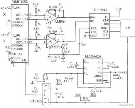
Dual-axis magnetic field sensor application circuit is shown. A two-axis magnetic sensor HMC1002 and two pieces of AMP04 (A1, A2) are used to simultaneously measure the magnetic field of X-axis direction and Y-axis direction. Dual-direction voltage signal output by HMC1002 can be respectively amplified by A1 and A2. And they are connected to the 12 bit A / D converter TLC2543 analog input and reference terminal. Then it is connected to μP through the interface circuit. MAX662A is the efficient DC / DC converter, which raises + 5 V power supply to 10 V power supply. The 10 V power supply can power the drive IRF7105. The input signal of the drive is from the μP.
(View)
View full Circuit Diagram | Comments | Reading(2580)
single-axis magnetic field sensor with serial interface circuit
Published:2011/8/11 4:41:00 Author:John | Keyword: single-axis magnetic field sensor, serial interface
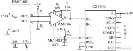
Single-axis magnetic field sensor with serial interface circuit is shown. The circuit's output stage uses a 16-bit A / D converter CS5509, which can be equipped with a microprocessor or microcontroller through the interface circuit. The output voltage (Uo) of the AMP04 is connected to the analog input of CS5509. MC1403-type band-gap reference voltage source powers CS5509 with 2.5V reference voltage.
(View)
View full Circuit Diagram | Comments | Reading(1516)
four-and-a half display voltage meter formed by the single-chip CMOS IC circuit
Published:2011/8/11 4:13:00 Author:John | Keyword: four-and-a half display voltage meter, single-chip, CMOS, IC
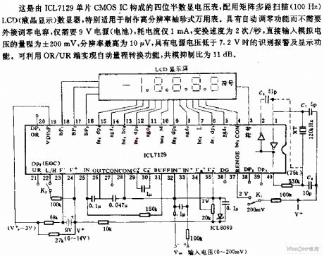
This is the four-and-a half display voltage meter composed of the ICL7129 monolithic CMOS IC. It is equipped with the multi-scan matrix (100Hz) LCD (liquid crystal display) digital device. It is especially for production of high-resolution pocket multimeter. It has the auto-zero function without the need for external capacitors. Only a 9V power supply (battery) is required. The current consumption is only 1mA and the changing speed is 2 times / second. Its direct input analog voltage range is ± 200 mA and its maximum bit resolution is 10μV. When the power supply voltage is lower than7.2V, the alarm and display functions can be identified. (View)
View full Circuit Diagram | Comments | Reading(2406)
CMOS four-and-a half decimal counter circuit
Published:2011/8/11 3:54:00 Author:John | Keyword: CMOS four-and-a half decimal counter
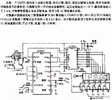
This is the CMOS four-and-a half decimal counter, which includes the count, the latch, by-bit scanning output circuit and protection circuit inside. Only an external capacitor is needed to change the scanning speed freely. Its power supply voltage is within 3 ~ 10V and its static current consumption is less than 1mA. The counting frequency ranges from dc to several megahertz. And it uses DIP-16 pin package.
The counting pulses are coupled to DG6010 from high-speed photodiode isolator SL950 to count. Then the BCD code sent by DG6010 is converted into 7-segment signal by CC4511B. Then the 7-segment signal is added to four-phase LED to display.
(View)
View full Circuit Diagram | Comments | Reading(1509)
LCD direct drive circuit
Published:2011/8/11 3:31:00 Author:John | Keyword: LCD, direct drive

Every phase of LCD has the separate counter, latch, decoder and driver. Excitation signal is also fed back to the floor plate of LCD (liquid crystal display). When the display segment is disconnected, the floor plate and display segment drive signal to be with the same phase and amplitude. So there is no voltage across the segment. When the segment is encouraged, the excitation signal phase is greater than 180 °. So the square-wave voltage is two times more than the IC supply voltage. Dual-counter BCD from the cascade MC14518 can input signals by generating BCD code.
(View)
View full Circuit Diagram | Comments | Reading(1082)
NISSAN new Teana audio (with navigation system) circuit(f)
Published:2011/7/28 4:12:00 Author:John | Keyword: navigation system, new Teana audio
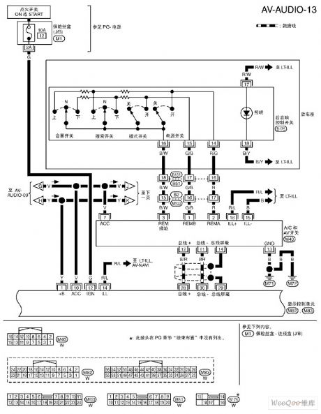
NISSAN new Teana audio (with navigation system) circuit(e) is shown.
(View)
View full Circuit Diagram | Comments | Reading(788)
A number explicit expression timer circuit diagram
Published:2011/8/11 2:24:00 Author:Rebekka | Keyword: expression timer

Digital display type timer has a clear display. It will show the digital pulse signal by digital display tube when the signal is coded by the number implement. This circuit introduces a digital display type timer. It's display unit is decided by the time-base signal. It can be a second and also can be the points or hour . But the digital display type timer for hour is too big. (View)
View full Circuit Diagram | Comments | Reading(1180)
| Pages:552/2234 At 20541542543544545546547548549550551552553554555556557558559560Under 20 |
Circuit Categories
power supply circuit
Amplifier Circuit
Basic Circuit
LED and Light Circuit
Sensor Circuit
Signal Processing
Electrical Equipment Circuit
Control Circuit
Remote Control Circuit
A/D-D/A Converter Circuit
Audio Circuit
Measuring and Test Circuit
Communication Circuit
Computer-Related Circuit
555 Circuit
Automotive Circuit
Repairing Circuit