
Circuit Diagram
Index 558
The implanted amplifier circuit
Published:2011/8/15 23:47:00 Author: | Keyword: implanted amplifier

The amplifier is used in the emitter which is implanted in human bodies, so the LEV of the brain and heart can be monitored. The circuit works when the voltage is lower than 1.35V. The voltage gain is 2000, when the source impedance is 10MΩ, the equivalent input noise is only 10*10 -6Vp-p. The current of Trl is too low, so the band width is only 5kHz or so, but it is enough for biological use.
(View)
View full Circuit Diagram | Comments | Reading(753)
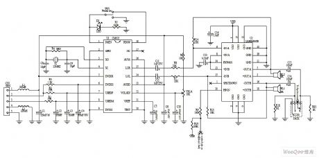
TL431 Basic Application Circuit
Published:2011/8/11 23:23:00 Author:Robert | Keyword: Basic, Application
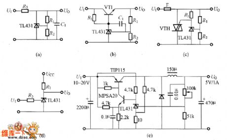
The TL431 basic application circuit is shown in the picture.
(a)Parallel voltage regulator circuit. (b)Series voltage regulator circuit. (c)Over-voltage protection circuit by using VTH. (d)Convertor with wide temperature compensationvalue. (e)Voltage regulator power with output 5V/1A. (View)
View full Circuit Diagram | Comments | Reading(8229)
ICBT Grid Electrode Driving Control Power Circuit
Published:2011/8/16 10:35:00 Author: | Keyword: ICBT, Grid Electrode, Driving, Control, Power
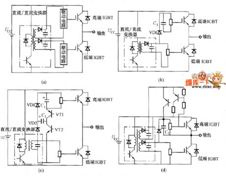
The ICBT grid driving circuit itself is using the hybrid method. Its internal optocoupler type, high-voltage type IC would make it small. But the control power, which provide power for the grid electrode driving circuit, should use the transformer and smoothing capacitor and so on. For the driving circuit overall miniaturization, it should consider the miniaturization of these elements. So it would take different ways for the control circuit, which are shown in the picture. The picture (a) is transformer method. It is a stable power of which the high and low side IGBT can get the same voltage. The picture (b) is the bootstrap method. The C1 is the bootstrap capacitance. The VD1 should select the high-voltage diode. The inverter's output duty cycle shouldn't be 100%. (View)
View full Circuit Diagram | Comments | Reading(1530)
The long-distance body heat probe circuit
Published:2011/8/17 22:32:00 Author: | Keyword: long-distance, body heat probe

The probe is fixed with the P2288 infrared heat sensor which is produced by Hamamatsu Corp. The device has two modes which are aim detection mode and still detection mode, its detecting range is 100m and it doesn't react to the constant heat. The heat sensor PYR1 outputs signal to the input terminal of IC1, of which the magnification factor of IC1-a is about 2500, the frequency reaction is 0.1~10Hz, then the signal output by IC1-b is magnified by 40 times by Q1. The output of Q1 is sent to the outlet of AC voltmeter by C11, so the millvoltmeter can be inserted and read out the signal power value. (View)
View full Circuit Diagram | Comments | Reading(1428)
The multi-function electric stimulation therapeutic apparatus circuit
Published:2011/8/18 3:49:00 Author: | Keyword: multi-function, electric stimulation, therapeutic apparatus

IC1 generates the clock pulse of 256Hz, and its output is added on the 1-pin of IC2. IC2(CD4024) is a binary pulse counter/frequency distributor, whose output frequency is 128~2Hz. The pulse signal output by IC2 is sent to the 1-pin of IC3(CD4024), the output terminals of 4, 5 and 6 generate the pulses of 8s, 16s and 32s respectively, which are to control the 8-bit electric switch in IC4(CD4051) and make the switch conducted every 8s in sequence. The output of IC1 and IC2 are linked to one terminal of IC4 8-bit e-switch. (View)
View full Circuit Diagram | Comments | Reading(2213)
IGBT Grid Electrode Driving Circuit
Published:2011/8/13 7:03:00 Author:Robert | Keyword: IGBT, Grid Electrode, Driving

The picture shows the IGBT grid electrode driving circuit practical example. This circuit should be noted the following tips:(1)PC should choose the optical coupler which has fast response speed and strong ability to remove the common-mode noise, such as HCP4504, TLP559 and so on.(2)It should take measures to aviod the optical coupler's error action caused by the driving power variation. For example, the R1 and C1 can make up the anti-interference circuit.(3)The C2 and C4 are the smoothing capacitances used for the driving power. Its capacitance value is chosen to be 100 times of Cies (Cies is the input capacitance of the IGBT). The C3 and C6 are in parallel with the C2 and C4 which should have the good high-frequency features. They are used to filter the high-frequency noise. (View)
View full Circuit Diagram | Comments | Reading(3088)
The generating circuit based on sine waves
Published:2011/8/11 8:17:00 Author:Borg | Keyword: generating circuit, sine waves

The generating circuit based on sine waves is shown as above.
(View)
View full Circuit Diagram | Comments | Reading(834)
The sine wave oscillator circuit based on stability
Published:2011/8/11 8:19:00 Author:Borg | Keyword: sine wave oscillator, stability

The sine wave oscillator circuit based on stability is shown as above.
(View)
View full Circuit Diagram | Comments | Reading(710)
The Fukang engine igniter and relevant electric element control circuit
Published:2011/8/11 21:10:00 Author:Borg | Keyword: engine igniter, electric element, control circuit

The Fukang engine igniter and relevant electric element control circuit (View)
View full Circuit Diagram | Comments | Reading(614)
The Fukang charging and starting circuit
Published:2011/8/11 21:11:00 Author:Borg | Keyword: Fukang, charging, starting

The Fukang charging and starting circuit (View)
View full Circuit Diagram | Comments | Reading(594)
The self-made NI-MH rechargeable battery circuit
Published:2011/8/15 21:34:00 Author: | Keyword: NI-MH rechargeable battery

1.The form of Vref When the external power passes the outlet X and the diode VD1, it is then filtered by capacitor C1. VD1 fulfills the function of protection, it can prevent TL431 from being broken when the external power is connected reversely. R3 , R3, R4, R5 and TL431 form the Vref, according to the figured parameter Vref= 2.5×(100+820)/820=2.80(v), this data is designed for the Ni-MH rechargeable battery(the voltage of a NI-MH rechargeable cell is about 1.40V when it is full). 2.large current charge (1)the working principles When the power is on, the power supply indicator LED(VD2) is glowing. (View)
View full Circuit Diagram | Comments | Reading(1115)
IGBT Absorbing Circuit
Published:2011/8/16 10:13:00 Author: | Keyword: IGBT, Absorbing

Except the large-capacity devices, the IGBT absorbing circuit has two kinds which are shown in the picture. And, the picture (a) is the most simple capacitance absorbing circuit (C absorbing circuit). The main circuit's inductor and capacitor C1 would generate the resonance. If C1 is too small or the main circuit inductor is too large, the DC power wire's voltage would have a big variation. The picture (b) shows the resistance-capacitance diode absorbing circuit (RCD absorbing circuit) which is complex. But the DC power wire's voltage has small variation. When the main circuit inductor is big, this absorbing circuit's performance of limiting the surge voltage would be good. But it should note the function of diode VD1. If having wrong selection it would generate the voltage oscillation. (View)
View full Circuit Diagram | Comments | Reading(1067)
IGBT Driving Circuit Composed Of EXB840
Published:2011/8/11 6:44:00 Author:Robert | Keyword: IGBT, Driving
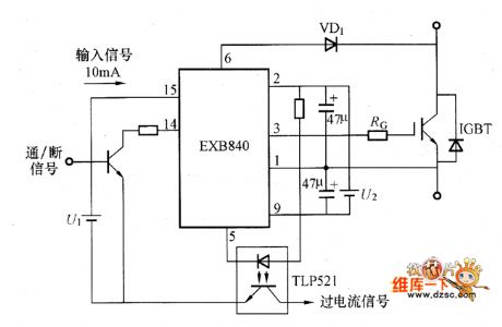

The IGBT driving circuit composed of EXB840 is shown in the picture. (View)
View full Circuit Diagram | Comments | Reading(1488)
Wide Range Duty Cycle Grid Electrode Isolated Driving Circuit
Published:2011/8/18 5:46:00 Author: | Keyword: Wide, Duty Cycle, Grid, Electrode, Isolated, Driving

The picture shows the wide range duty cycle grid electrode isolated driving circuit by using the pulse transformer. In the circuit, the transformer T1's inductance and resistance R1 make up the differential circuit which would generate the power MOSFET's grid electrode driving voltage. If the transformer T1's secondary side generating the positive polar pulse (which means the high side is positive and the low side is negative), the VD1 would be conducted and charge the keeping capacitance CH and VF1's input capacitance Ciss. At this time the VT1's leakage current between grid electrode and the source electrode is very small. So even the input differencial pulse voltage is 0V, it would also keep the charging voltage. (View)
View full Circuit Diagram | Comments | Reading(837)
The imported USB serial switch cirucit
Published:2011/8/11 21:14:00 Author:Borg | Keyword: imported USB, serial switch cirucit
The imported USB serial switch cirucit is shown as above.
(View)
View full Circuit Diagram | Comments | Reading(656)
The USB multimedia 2.5W+2.5W voice box design circuit
Published:2011/8/11 21:17:00 Author:Borg | Keyword: multimedia, voice box, design circuit
The USB multimedia 2.5W+2.5W voice box design circuit is shown as above.
(View)
View full Circuit Diagram | Comments | Reading(830)
The USB mouse design circuit
Published:2011/8/11 21:18:00 Author:Borg | Keyword: USB mouse, design circuit

The USB mouse design circuit is shown as above.
(View)
View full Circuit Diagram | Comments | Reading(1397)
The simplest capacitor step-down dirve LED circuit
Published:2011/8/11 21:26:00 Author:Borg | Keyword: capacitor, step-down dirve, LED

This is a simplest capacitor step-down applicational circuit, in the circuit, the AC voltage is rectified by 2 backward parallel LEDs after it is stepped down. The circuit can be used in lighting lamps, key indicators and other situations with low standards.
(View)
View full Circuit Diagram | Comments | Reading(1771)
Grid Electrode Driving Circuit By Using Pulse Transformer
Published:2011/8/17 21:31:00 Author: | Keyword: Grid, Electrode, Driving, Pulse, Transformer

There are many advantages for the grid electrode driving circuit by using the pulse transformer. For example, the pulse transformer can make up a simple grid electrode isolated circuit and do not distinguish the high and low side driving circuit. The pulse transformer could also transmit the power, and the high-side driving circuit does not need the auxiliary power. The grid electrode driving conditions could be set freely.The high and side driving circuit could use the circuit with the same structure. In half-bridge circuit it could use the pulse transformer to make up the symmetrical drive circuit and so on.The picture shows the grid electrode driving circuit by using the pulse transformer. This circuit pulse transformer T1 could use the center tap method, and do the switching work by the transistor or power MOSFET. It is always used in the positive excitation conversion's switching power. (View)
View full Circuit Diagram | Comments | Reading(669)
The 3.3V charge battery power supply applicational circuit
Published:2011/8/11 21:27:00 Author:Borg | Keyword: charge battery, power supply, applicational circuit

The 3.3V charge battery power supply applicational circuit is shown in the figure.
(View)
View full Circuit Diagram | Comments | Reading(639)
| Pages:558/2234 At 20541542543544545546547548549550551552553554555556557558559560Under 20 |
Circuit Categories
power supply circuit
Amplifier Circuit
Basic Circuit
LED and Light Circuit
Sensor Circuit
Signal Processing
Electrical Equipment Circuit
Control Circuit
Remote Control Circuit
A/D-D/A Converter Circuit
Audio Circuit
Measuring and Test Circuit
Communication Circuit
Computer-Related Circuit
555 Circuit
Automotive Circuit
Repairing Circuit