
Circuit Diagram
Index 541
Furnace temperature control circuit composed of the AD590
Published:2011/8/23 22:27:00 Author: | Keyword: Furnace, temperature control

The furnace temperature control circuit which is composed of the AD590 is as shown in the figure. In this circuit, the output current of AD590 is compared with the benchmark current at the reverse phase input port of the Al, this current is decided by the -lOV stable voltage of the high performance voltage-regulator tube AD581; A2 is the filter; A3 is the addition calculator, it amplifies the error signal and adjusts the pulse width drive heater RL according to the temperature value. In order to get the most stable dynamic characteristics, we use the silicon grease to paste the AD590 on the heater RL. Due to the output current sensor AD590 is proportional to the temperature, we can adjust the film resistance of the chip, when the temperature is 298·2K(25℃), the output current is 298·2μA. So we can control the temperature of the furnace.
(View)
View full Circuit Diagram | Comments | Reading(1386)
Multi-channel Display Circuit Composed of CD4017
Published:2011/8/18 6:53:00 Author: | Keyword: Multi-channel, Display
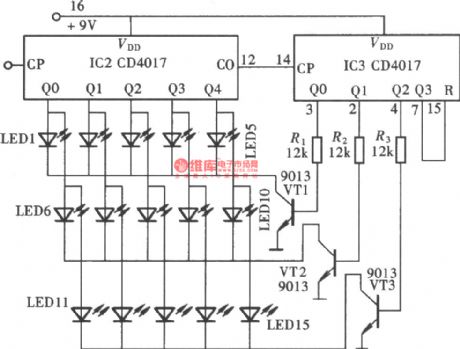
As seen in the pciture, when two CD4017's output terminals are connected in a certain combination and are added some corresponding control circuits, there will be a multi-channel output states display circuit. The circuit consists of two CD4017, three transistors and fifteen LEDs, and it is 15 circuits output display circuit. In the circuit, IC2 uses 5 output terminals of Q0-Q4. IC3 uses 3 output terminals of Q0-Q2. IC2's 5 output terminals are divided into 3 groups which are connected 15 LEDs in parallel. Every group of 5 LEDs are controlled by IC3's 3 output terminals through VT1-VT3 and are displayed in 3 groups. (View)
View full Circuit Diagram | Comments | Reading(5169)
The FM circuit composed of the NE555
Published:2011/8/23 22:28:00 Author: | Keyword: FM circuit

The FM circuit composed of the NE555 is as shown in the figure. By changing the charging current of the NE555 self-excited multivibrator, we can do the frequency modulation. This circuit is the current mueller circuit that is composed of VT1 and VT2, and it can produce the charging current in the charging circuit, the current is decided by R1 and RP1. The low frequency modulation signal and the offset current IB are overlied to make the oscillation frequency change. The current mueller circuit need to use the geminate transistor.
(View)
View full Circuit Diagram | Comments | Reading(1967)
Temperature monitoring circuit composed of the AD590
Published:2011/8/17 21:05:00 Author: | Keyword: Temperature, monitoring circuit

The temperature monitoring circuit which is composed of the AD590 is as shown in the figure, it uses the 9V battery as the power supply. In this circuit, A1 is the current/voltage conversion and voltage amplifier circuit, the monitoring temperature range is -50 to +150℃, the output port of A1 is connected with the positive input port of the digital multimeter (monitor circuit). A2 is the O℃ benchmark and temperature correction circuit, the output port of it is connected with the negative input port of the digital multimeter. The AD580 is one kind of precision voltage reference device, it supplies the reference voltage to the A2-A4. The MD590 has the correction error, this has the relationship with the device level, you can use the RP1(500Ω) fine-tuning potentiometer to eliminate the error when the temperature is 25℃.
(View)
View full Circuit Diagram | Comments | Reading(1282)
Temperature detection circuit composed of the diode temperature sensor
Published:2011/8/23 22:29:00 Author: | Keyword: Temperature detection, diode, temperature sensor

The temperature detection circuit which is composed of the diode temperature sensor is as shown in the figure. In this circuit, the VD is used as the temperature sensor, the VD2 is the temperature compensation diode. The bridge type circuit is composed of the VD, VD2, R1, R2, R3 and RP1, the compensation current of the RP1 fixed diode is about 3uA. Every time when the temperature changes for 1℃, the bridge circuit outputs the 2mV voltage, this voltage is amplified by A1 and encourages the VT1 through VD3, and it drives the relay through VT1.
(View)
View full Circuit Diagram | Comments | Reading(3150)
Oscillating Circuit Composed of CD4518
Published:2011/8/11 8:13:00 Author:Sue | Keyword: Oscillating Circuit
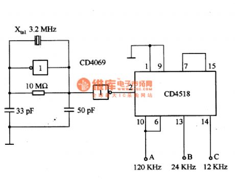
The picture shows oscillating circuit which composed of CD4518. The circuit is composed of BCD counter CD4518 and crystal oscillator(3.2MHZ). A,B,C terminals will output signals of frequency of 120KHZ, 241KHZ,12kHZ respectively. The working voltage is 10V. (View)
View full Circuit Diagram | Comments | Reading(2355)
Multi-channel Voltage Cyclic Detection Circuit(NE555,CD4066)
Published:2011/8/18 6:37:00 Author: | Keyword: Multi-channel Voltage, Cyclic Detection
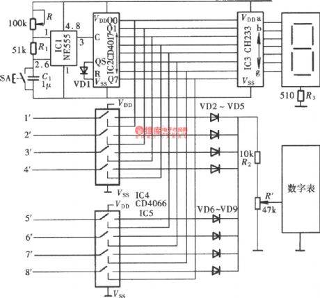
The multi-channel voltage cyclic detection circuit is used to realise integrated control of the production facility. The device can detect every production device's working voltage automatically in a given time interval so that the watchstander can know the working state of the device according to the detection result and handle the problem in time when any irregularity occurs. The picture shows the circuit which consists of cyclic detection pulse generator, cyclic detection pulse distributor, cyclic detection channel optional switch and channel display. The largest cyclic detection channel is eight-channel. (View)
View full Circuit Diagram | Comments | Reading(1650)
Rock Illuminations Controller Composed of NE555
Published:2011/8/18 6:18:00 Author: | Keyword: Rock Illuminations, Controller

The picture shows the rock illuminations control circuit. The controller consists of voltage reduction and rectification circuit, 555 multivibrator, illuminations control circuit.
For the multivibrator which is composed of 555 and D4,D3,W1,C2, by adjusting W1, the circuit's charging and discharging time constant can be changed which will make the alternating square wave's duty ratio 2:1. When IC(555)'s pin 3 output low level, the inside corresponding discharging tube's discharging function will make pin 7 have low level which will illuminated LED1 and relay J2 will be connected. Then the first group of illuminations will be turned on by the control. (View)
View full Circuit Diagram | Comments | Reading(539)
Square wave and sawtooth wave generation circuit composed of the MAM4162
Published:2011/8/23 22:29:00 Author: | Keyword: Square wave, sawtooth wave, generation circuit
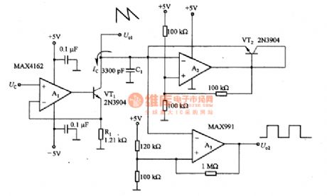
The square wave and sawtooth wave generation circuit composed of the MAM4162 is as shown in the figure. The linearity of this kind of circuit is higher than 1%, the dynamic range can be 80dB. In the circuit, the voltage controlled current source is composed of the A1, VT1 and R1. The capacitance C1 discharges through the current Ic until the voltage of it is reduced to 1.66V, the comparator A2 outputs the +5V voltage. The current of VT2 charges the capacitance C1 until the voltage of it is 3.33V, the output of A2 closes to the ground level. When the control voltage Uc=1.66V, the output frequency is maximum. You can change the value of R1 and C1 to make it output the expected value, the upper limit frequency is limited by the rise time of A2.
(View)
View full Circuit Diagram | Comments | Reading(2281)
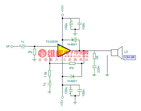
15W Amplifier Circuit
Published:2011/8/11 5:55:00 Author:Sue | Keyword: Amplifier

The picture shows the 15W amplifier circuit. (View)
View full Circuit Diagram | Comments | Reading(1493)
8W Amplifier Circuit
Published:2011/8/11 5:53:00 Author:Sue | Keyword: Amplifier
View full Circuit Diagram | Comments | Reading(563)
Temperature measurement circuit composed of the platinum RTD
Published:2011/8/23 22:29:00 Author: | Keyword: Temperature measurement, platinum RTD

The temperature measurement circuit which is composed of the platinum RTD is as shown in the figure 3-14. In this circuit, the RT is used as the temperature sensor, it is designed as one kind of 100Ω(25℃) platinum RTD. This kind of platinum RTD has high stability and very high precision temperature coefficient, so the +5V power supply supplies the 1mA current to the RT through R1, and we can get the relationship between the temperature and output signal voltage, if the temperature changes 1℃, the circuit will produce -385μV signal voltage. The proportion type measuring bridge circuit is composed of the R2, RP1 and R3, A1 is the bridge circuit amplifier which can be used as the digital control potentiometer of the feedback component to capture and keep the initial reference temperature T0 automatically.
(View)
View full Circuit Diagram | Comments | Reading(2112)
Random code generation circuit composed of the LTC1340
Published:2011/8/23 22:29:00 Author: | Keyword: Random code, generation circuit
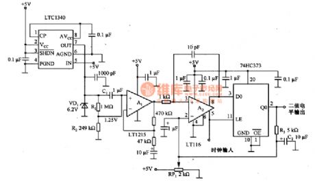
The random code generation circuit which is composed of the LTC1340 is as shown in the figure. This circuit uses the 6.2V voltage-regulator diode VD1 to produce the random noise with the best features. We can find that this circuit outputs the best noise at the bending place of the zener diode characteristic curve, it is the starting place of the 6.2V stable voltage. The operating voltage of the circuit is +5V. In order to let the VD1 get the 6.2V stable voltage, we use the LTC1340 as the boost converter to improve the +5V to +8V (the output voltage of the pin-7 is 9.2V). The resistors R1 and R2 supply the 1.25V bias voltage to A1 to make it match with the input common-mode signal range of the comparator A2.
(View)
View full Circuit Diagram | Comments | Reading(629)
The solar energy water heater temperature control circuit composed of the thermistor
Published:2011/8/23 22:29:00 Author: | Keyword: solar energy, water heater, temperature control, thermistor

The solar energy water heater temperature control circuit which is composed of the thermistor is as shown in the figure. In this circuit, the thermistor RT1 detects the temperature of the water in the collector, RT2 detects the temperature of the water in the storage device. The temperature changes into the corresponding voltage through the thermistor, and this voltage adds to the input port of the comparator Aa, the output comparison result of A1 controls the circulation pump through the relay K1. The resistance value of the (R(RPl)+Rl) decides the action of the pump, in the actual situation, the resistance value is about 12-18Ω. For example, when the resistance value of (R(RPl)十Rl) is 13Ω, the water temperature of the storage device is 30℃.
(View)
View full Circuit Diagram | Comments | Reading(2544)
Channel 6 Input Mixer Circuit
Published:2011/8/14 6:45:00 Author:Sue | Keyword: Channel 6, Input Mixer

View full Circuit Diagram | Comments | Reading(716)
Musical Lantern Controller(NE555,CD4066,CD4017)
Published:2011/8/18 5:50:00 Author: | Keyword: Musical Lantern, Controller

The picture shows the musical lantern control circuit. The controller consists of acoustic electric transduce and amplifying circuit, clock pulse generator, counting circuit and control circuit. The pickup transmitter MIC willconvert the acoustic signal to electric signal which will be put onto four circuits of analog switch CD4066(IC3) after it is amplified by BG1-BG3.
The clock pulse generator consists of IC1(555), W1,R1,R2,D1 and C1. The circuit's signalperiod T=0.693(Rw1+R1+R2)C1, and the correspondence period T in the picture varies in the range of 0.5-5s, among which 555(pin 3) is output and put on IC2 to work as CP pulse. (View)
View full Circuit Diagram | Comments | Reading(1278)
CHANGHONG N2918 Power Supply Circuit
Published:2011/8/11 7:59:00 Author:Sue | Keyword: Power Supply

The picture shows CHANGHONG N2918 power supply circuit. (View)
View full Circuit Diagram | Comments | Reading(848)
Multi-functional vision protector circuit
Published:2011/8/23 22:29:00 Author: | Keyword: Multi-functional, vision protector

The Multi-functional vision protector circuit
(a) is the infrared transmitter circuit; (b) is the infrared receiver circuit
(View)
View full Circuit Diagram | Comments | Reading(925)
CHANGHONG CH-10 Power Supply Circuit
Published:2011/8/11 7:56:00 Author:Sue | Keyword: Power Supply

View full Circuit Diagram | Comments | Reading(1006)
The Mazda 95PROBE charging system circuit
Published:2011/8/14 8:42:00 Author:Christina | Keyword: Mazda, charging system circuit
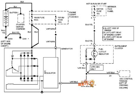
The Mazda 95PROBE charging system circuit is as shown in the figure:
(View)
View full Circuit Diagram | Comments | Reading(1875)
| Pages:541/2234 At 20541542543544545546547548549550551552553554555556557558559560Under 20 |
Circuit Categories
power supply circuit
Amplifier Circuit
Basic Circuit
LED and Light Circuit
Sensor Circuit
Signal Processing
Electrical Equipment Circuit
Control Circuit
Remote Control Circuit
A/D-D/A Converter Circuit
Audio Circuit
Measuring and Test Circuit
Communication Circuit
Computer-Related Circuit
555 Circuit
Automotive Circuit
Repairing Circuit