
Circuit Diagram
Index 561
Boost Voltage Convertor Circuit Composed Of LTC1700
Published:2011/8/14 3:41:00 Author:Robert | Keyword: Boost, Voltage, Convertor
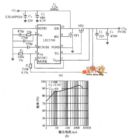
The picture shows the convertor circuit composed of LTC1700. This is a simple circuit to convert the 3.3V voltage to 5V voltage. The LTC1700 is a PWM integrated controller with MSOP package, 530kHz working frequency and current mode. Its effciency could be maximum 95%. And it also has the new function that not using resistor to detect main MOSFET current. So it needn't the sensing resistor. In the circuit shown in picture (a), it only consume 180pA current in the dormancy mode. So it is best suitable for the portable type devices standby power-saving mode. For the practical products, if the input/output ports connect the LC filter, it would make the noise lower.
(View)
View full Circuit Diagram | Comments | Reading(870)
Convertor Circuit Composed Of TPS54610
Published:2011/8/13 6:19:00 Author:Robert | Keyword: Convertor

The picture shows the low input voltage to low output voltage DC-DC convertor. It uses the PWM comtrol method and the oscillation frequency is set to be 350kHz or 550kHz. Its input voltage is 5V and output is 3.3V/61A.
The TPS54610 uses TSSOP package. It has internal high-end MOSFET and low-end MOSFET. All the semiconductor devices needed by the power are modularized. It can make up the new buck convertor. So its conversion efficiency is very high.
The picture shows the convertor circuit composed of TPS54610. (View)
View full Circuit Diagram | Comments | Reading(986)
Voltage Driving MOSFET Grid Electrode Principle Circuit
Published:2011/8/17 7:01:00 Author: | Keyword: Voltage, Driving, MOSFET, Grid, Electrode, Principle
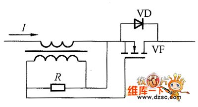
The MOSFET grid electrode driving principle circuit by using the current transformer secondary winding induced voltage is shown in the picture. The current would firstly circulate through the MOSFET parasitic diode. So the current transformer secondary winding would generate the induced voltage. When this voltage is beyond the threshold voltage, it would charge the MOSFET grid electrode. And the current would be conducted through MOSFET channel. Firstly the current which through the parasitic diode would generate the voltage drop about 1V. But when it is through the MOSFET channel, only its conducted resistance would generate a low voltage drop and there are no other voltage drop. That is the synchronous rectification. The principle circuit in the picture can not be used in the high-speed switching rectifier without any changing. (View)
View full Circuit Diagram | Comments | Reading(1162)
Synchronous Rectifier Buck Chopper Circuit
Published:2011/8/13 6:10:00 Author:Robert | Keyword: Synchronous, Rectifier, Buck, Chopper
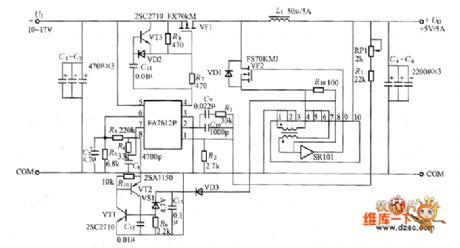
The circuit, which uses the synchronous rectifier buck chopper and has the output of 5V/5A, is shown in the picture. In the circuit, VF2 is the MOSFET used for synchronous rectifier. The SR101 is synchronous driving module. If connecting the diode VD1's positive electrode to the ground it would make up the traditional buck chopper circuit.
The picture shows the synchronous rectifier buck chopper circuit. (View)
View full Circuit Diagram | Comments | Reading(1672)
DC-DC Convertor Circuit Composed Of BIC1421
Published:2011/8/11 6:37:00 Author:Robert | Keyword: DC-DC, Convertor

The DC-DC convertor circuit composed of BIC1421 is shown in the picture. (View)
View full Circuit Diagram | Comments | Reading(973)
Practical Switch Voltage Regulator Power Supply Circuit With Positive Incentives Convertor Method
Published:2011/8/12 18:43:00 Author:Robert | Keyword: Practical, Switch, Regulator, Power Supply, Positive, Incentives, Convertor, Method

The practical switch voltage regulator power supply circuit is shown in the picture. The positive incentives convertor method's main features are:1.The transformer winding's primary and secondary has the same polarity.2.When VT1 is connected, the current i1 would be through Np. At the same time the output side has current i2 conducted, and the output current is Io. Also the inductor L is cumulating the energy.3.When the VT1 is disconnected, the L's opposite EMF would make the current conducted through VD2.4.The output side rectifier circuit is inductor input type whose switching frequency is beyond 100kHz.
The picture shows the practical switch voltage regulator power supply circuit with positive incentives convertor method. (View)
View full Circuit Diagram | Comments | Reading(1317)
The typical high-voltage flashlight circuit
Published:2011/8/18 8:09:00 Author: | Keyword: high-voltage flashlight


1. The high-voltage flashlight circuit The high-voltage flashlight generate high voltage through the oscillating circuit and booster transformer, and the energy is stored by the large volume storage, which releases and inducts high voltage transiently, so the inert gases are triggered and emitting the pulse light, which is how the high transient power is got. In figure 1 is the prototype of a flashlight, which consists of a glass cover full of xenon, both the negative and positive are dipped in the xenon, but the trigger pole is connected with the surface of the light without dipping in the xenon.
(View)
View full Circuit Diagram | Comments | Reading(850)
The electron tube crossing balance inverting phase circuit
Published:2011/8/11 21:53:00 Author:Borg | Keyword: electron tube, crossing balance, inverting phase
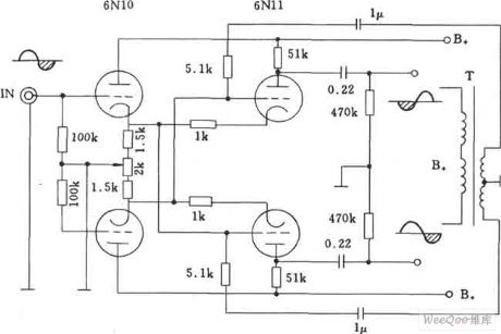
The electron tube crossing balance inverting phase circuit is also called Zell inverting phase circuit, in which 6N10 and 611 can be used as the pre-amplifier and phase inverter, and the circuit can be connected with the rear-end power amplifier tube installed with 300B.
(View)
View full Circuit Diagram | Comments | Reading(1415)
The 4-bit and 9-stage LED display driver LED circuits
Published:2011/8/18 7:26:00 Author: | Keyword: LED, display driver


MAX6958/MAX6959 are 4-bit and 9-stage LED display driver LED circuits, they are equipped with the 6-bit PWM(64-stage) brightness technology, which can adjust the average currents of all the LEDs at the same time. By expanding MAX6958/MAX6959 functions, the single pixel stage(LED) control can be fulfilled. MAX6958/MAX6959 are equipped with a multi-line reuse technology with a few pins, it only needs 10 drive pins to drive 36 stages. The standard connection method of MAX6958/MAX6959 is shown in the table.
(View)
View full Circuit Diagram | Comments | Reading(1325)
The Li-ion battery drive white light LED circuit composed of LT3202 electric charge pump
Published:2011/8/18 7:43:00 Author: | Keyword: Li-ion battery, white light LED, electric charge pump
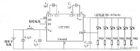
LTC3202 is an electric charge pump without gates which is produced by Linear Technology Corp., in the figure is the Li-ion battery drive white light LED circuit composed of LT3202 electric charge pump. To solve the problem of noise, LTC3202 is equipped with linear regulation technology, which can make sure the converting capacitance charge and discharge volume meet the need of the loading current, and it can keep it at the constant volume in each period, so they won't generate the audio weight.
Figure The Li-ion battery drive white light LED circuit composed of LT3202 electric charge pump (View)
View full Circuit Diagram | Comments | Reading(2439)
The high speed phase inverting amplifier circuit
Published:2011/8/11 21:54:00 Author:Borg | Keyword: high speed, phase inverting amplifier

The high speed phase inverting amplifier circuit is shown in the figure.
(View)
View full Circuit Diagram | Comments | Reading(642)
A 24V WMOS tube regulated powers supply circuit
Published:2011/8/11 21:56:00 Author:Borg | Keyword: WMOS tube, regulated powers supply

A 24V WMOS tube regulated powers supply circuit is shown as above.
(View)
View full Circuit Diagram | Comments | Reading(736)
Absorbing Capacitor Charging And Discharging Control Circuit
Published:2011/8/14 1:31:00 Author:Robert | Keyword: Absorbing, Capacitor, Charging, Discharging, Control

In the circuit shown in picture (a), VF1 is the primary side main MOSFET. The pulses from the PWM integrated controller can make it working in connected/disconnected mode. To make the VF2's connected/disconnected time be opposite to VF1, it adds the bidirectional time delay circuit S1. Now if the VF1 is in disconnected mode, the VF2 is in connected mode, the absorbing capacitor Cr would charge to the voltage between VF1's drain electrode and source electrode. So it also absorb the surge voltage on VF1. After the delay time, which is determined by the time delay circuit, the VF2 is disconnected. But at this time, the Cr two ports' voltage is equal to the voltage on VF1. So it is the zero-voltage and zero-current switching devices disconnected mode. (View)
View full Circuit Diagram | Comments | Reading(1398)
The winking kitten circuit
Published:2011/8/15 20:55:00 Author: | Keyword: winking kitten

The winking kitten circuitT1 and the external elements form an audio oscillating circuit which can simulate the sound of mew. T1, L1 and L2 form the common base inducting 3-terminal oscillator. When the base electrode of T1 is biased, the oscillating frequency of L1 and C2 is high, and it rises with the increasing of the bias, it sounds the tune rises up from low. When the base electrode of T1 is in the backward bias, the oscillator composed of L1 and C2 stops, therefore, the oscillator composed of L2 and C6 controls the working state and oscillating frequency of the oscillator consists of L1 and L2, so the sound of mew is simulated.
(View)
View full Circuit Diagram | Comments | Reading(599)
The NISSAN new Teana gear-shifting electromagnetic valve B circut
Published:2011/8/11 7:41:00 Author:Borg | Keyword: NISSAN, Teana, gear-shifting, electromagnetic valve

The NISSAN new Teana gear-shifting electromagnetic valve B circut (View)
View full Circuit Diagram | Comments | Reading(934)
The NISSAN new Teana fluid torque clutch magnetic valve circut
Published:2011/8/11 7:59:00 Author:Borg | Keyword: NISSAN, Teana, fluid torque clutch, magnetic valve

The NISSAN new Teana fluid torque clutch magnetic valve circut (View)
View full Circuit Diagram | Comments | Reading(790)
The NISSAN new Teana exceeding clutch magnetic valve circut
Published:2011/8/11 8:01:00 Author:Borg | Keyword: NISSAN, Teana, magnetic valve
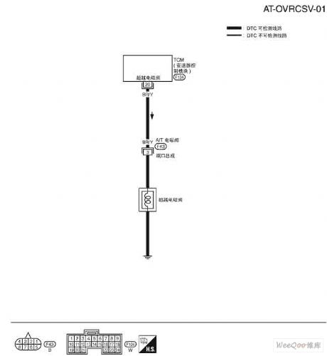
The NISSAN new Teana exceeding clutch magnetic valve circut (View)
View full Circuit Diagram | Comments | Reading(862)
The NISSAN new Teana A/T temperature sensor circuit and TCM power supply circut
Published:2011/8/11 8:03:00 Author:Borg | Keyword: NISSAN, Teana, temperature sensor, TCM, power supply
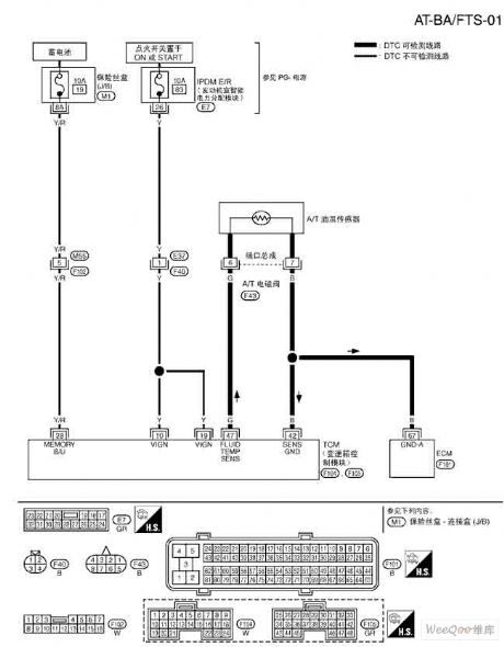
The NISSAN new Teana A/T temperature sensor circuit and TCM power supply circut (View)
View full Circuit Diagram | Comments | Reading(1321)
The NISSAN new Teana engine speed signal circut
Published:2011/8/11 8:04:00 Author:Borg | Keyword: NISSAN, Teana, engine speed
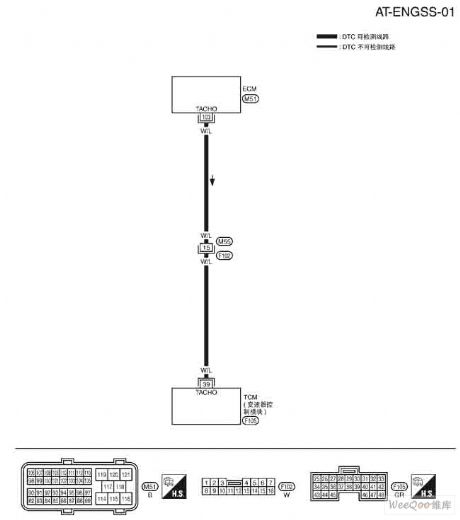
The NISSAN new Teana engine speed signal circut (View)
View full Circuit Diagram | Comments | Reading(848)
The NISSAN new Teana turbine rotating speed sensor circut
Published:2011/8/11 8:06:00 Author:Borg | Keyword: NISSAN, Teana, rotating speed sensor, turbine
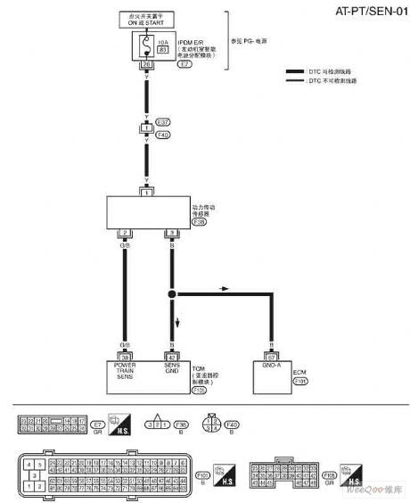
The NISSAN new Teana turbine rotating speed sensor circut (View)
View full Circuit Diagram | Comments | Reading(957)
| Pages:561/2234 At 20561562563564565566567568569570571572573574575576577578579580Under 20 |
Circuit Categories
power supply circuit
Amplifier Circuit
Basic Circuit
LED and Light Circuit
Sensor Circuit
Signal Processing
Electrical Equipment Circuit
Control Circuit
Remote Control Circuit
A/D-D/A Converter Circuit
Audio Circuit
Measuring and Test Circuit
Communication Circuit
Computer-Related Circuit
555 Circuit
Automotive Circuit
Repairing Circuit