
Circuit Diagram
Index 571
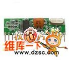
Superheterodyne Receiving Module RXB10
Published:2011/8/9 17:40:00 Author:Vicky | Keyword: Superheterodyne Receiving Module
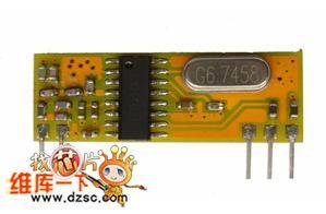
This RF wireless high-frequency receiving module, RXB10, is of high sensitiveness, which reaches -107dBm. The size is very small. It adopts ASK receiving mode, which is available for remote control, far- end control, remote control vehicle, data transmission, anti-theft alarm, home appliance control, wireless toy, vehicle-burglar alarm, wireless backup radar, remote garage gate control , remote motor-driven curtain, flexible door , remote strobe control. It is also an ideal choice GSM/GPS vehicular system set, industry control and systems of high complicated environmental requirement. It can take the place of infrared receptor. It can receive signals from omnidirectional direction and is easy to be added to general remote controls.
Key Feature:
Low-price 315/433.92/ receiving module
Built-in AGC
Low working voltage: 3.0V~5.5V
Low current: 5.7mA
High sensitiveness: -107dBm
Working temperature: -20℃~+85℃
Size of the appearance: 33×11×5mm (View)
View full Circuit Diagram | Comments | Reading(489)
Superheterodyne Receiving Module RXB11
Published:2011/8/9 17:42:00 Author:Vicky | Keyword: Superheterodyne Receiving Module
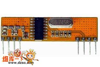
This RF wireless high-frequency receiving module, RXB11, is of high sensitiveness, which reaches -107dBm. It adopts ASK receiving mode, which is available for remote control, far- end control, remote control vehicle, data transmission, anti-theft alarm, home appliance control, wireless toy, vehicle-burglar alarm, wireless backup radar, remote garage gate control , remote motor-driven curtain, flexible door , remote strobe control. It is also an ideal choice GSM/GPS vehicular system set, industry control and systems of high complicated environmental requirement. It can take the place of infrared receptor. It can receive signals from omnidirectional direction and is easy to be added to general remote controls.
Key Feature:
Low-price 315/433.92/ receiving module
Built-in AGC
Low working voltage: 3.0V~5.5V
Low current: 5.7mA
High sensitiveness: -112dBm
Working temperature: -20℃~+85℃
Size of the appearance: 43.2×12.3×5mm
(View)
View full Circuit Diagram | Comments | Reading(878)
ASK/OOK Small-size Receiving Module RXB 14
Published:2011/8/9 17:43:00 Author:Vicky | Keyword: ASK/OOK Small-size Receiving Module
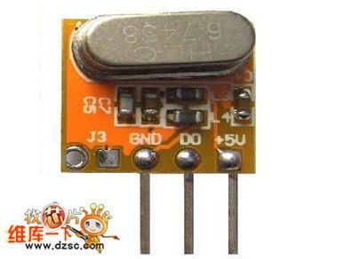
This RF wireless high-frequency receiving module, RXB14, is of high sensitiveness, which reaches -107dBm.The size is very small. It adopts ASK receiving mode, which is available for remote control, far- end control, remote control vehicle, data transmission, anti-theft alarm, home appliance control, wireless toy, vehicle-burglar alarm, wireless backup radar, remote garage gate control , remote motor-driven curtain, flexible door , remote strobe control. It is also an ideal choice GSM/GPS vehicular system set , industry control and systems of high complicated environmental requirement. It can take the place of infrared receptor. It can receive signals from omnidirectional direction and is easy to be added to general remote controls.
Key Feature:
Low-price 315/433.92/ receiving module
Built-in AGC
Low working voltage: 3.0V~5.5V
Low current: 5.7mA
High sensitiveness: -112dBm
Working temperature: -20℃~+85℃
Size of the appearance: 12×10.5×5mm
(View)
View full Circuit Diagram | Comments | Reading(943)
FSK/FM Receiving Module RXB6
Published:2011/8/9 17:45:00 Author:Vicky | Keyword: FSK/FM Receiving Module
Specification:
Frequency: 433.92/868MHZ
Working Voltage: 5V
Current dissipation: 7mA
Sensitiveness: -108dBm
Modulation mode: FSK
Applied fields: automotive-electronics, industrial control, and vehicular remote control etc. (View)
View full Circuit Diagram | Comments | Reading(939)
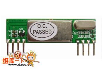
Superheterodyne Receiving Module RXB1
Published:2011/8/9 17:46:00 Author:Vicky | Keyword: Superheterodyne Receiving Module

RXB1 uses crystal frequency stabilization technology. It has relatively high frequency stability and uses RX3400 as the superheterodyne receptor. The receiving sensitiveness is high, the performance is stable, the current is low, the usage is easy, the size is small and it is cheap. The short antenna can be connected in the outside so that it is convenient to use. It can transmit direct current to the 2000BPS signal.
Product specification
Working voltage: DC 5V
Transmission rate: 2~4KBPS
Working mode: ASK (amplitude modulation)
Static current: 2~3mA (available to be connected to power-saving mode in the outside)
Receiving sensitiveness: -105dBm
Size of appearance: 43×12×5mm
Working temperature: -40℃~+70℃
Working frequency: 315 MHz; 433 MHz;
Output frequency stability: ±30PBM
Output signal: TTL electrical level
Ranking of pins: VSS、DATA、DATA、VDD VDD、VSS、VSS、ANT
Function of pins: GND: ground connection DATA: receiving data outputDATA: receiving data outputVDD : working power,DC 5V ; VDD: working power,DC 5V ; VSS: ground connectionVSS: ground connection ANT: antenna (View)
View full Circuit Diagram | Comments | Reading(693)
Superheterodyne Receiving Module RXB2
Published:2011/8/9 17:48:00 Author:Vicky | Keyword: Superheterodyne Receiving Module
Product specification
Working voltage: DC 5V ±10%
Transmission rate: 9.60KBPS
Working mode: ASK (amplitude modulation)
Static current: 4.6mA (it is available to be connected to power-saving mode in the outside and the start-up time is 250µs; the low-current shutdown mode is 50nA, which effectively saves power)
Receiving sensitiveness: -112dBm
Size of appearance: 43×12×5mm
Working temperature: -40℃~+85℃
Working frequency: 315MHZ~433.92MHZ
Output signal: TTL electrical level
Built-in -65dB RF image frequency rejection circuit
400KHz work bandwidth (the optimizing point of the image frequency rejection is 315/433/868MHz)
Integration of PPL built-in voltage-controlled oscillator (VOC) and loop filter
Selecting IF bandwidth by exterior filter
IF bandwidth is 150K, a refined receiving system from RF to number data output
Ranking of pins: GND、SHUT、DATA、VDD VDD、GND、GND、ANT
Function of pins: GND: ground connection SHUT: receiving data output/interface for connecting power-saving modeDATA: receiving data outputVDD : working power,DC 5V ; VDD: working power,DC 5V ; GND: ground connectionGND: ground connection ANT: antenna
(View)
View full Circuit Diagram | Comments | Reading(465)
Pulsed dc electronic fishing device
Published:2011/7/18 6:37:00 Author:Christina | Keyword: Pulsed, dc, electronic, fishing device

Debugging: you can connect a 100W incandescent lamp to the output port, you can adjust the 100K trimming resistance to make the lamp in the brightest state with the flashing feeling.
(View)
View full Circuit Diagram | Comments | Reading(1473)
Venturi Bridge Oscillation Circuit of LM377
Published:2011/8/3 6:44:00 Author:Michel | Keyword: Venturi Bridge, Oscillation Circuit

The picture 1 is Venturi bridge oscillation circuit of LM377.In the circuit,VT1 is used to limit the amplitude of the oscillating circuit and C3 and C6 are isolation capacitances.C5 is used to prevent high frequency oscillation.The series loop circuit composed of R2 and C2 and parallel loop circuit composed of R1 and C1 constitute postive feedback circuit.It can determine the oscillation frequency of the circuit.R10,R4,R6 and VT1 constitute negative feedback circuit and decides the limiting amplitude of the circuit.
When it is 10 KHz,the circuit distortion rate is lower than 1% and the distortion rate can be improved via adjusting the resistance value.According to the circuit parameters,the effective output voltage is 7.5V when it is 60Hz. (View)
View full Circuit Diagram | Comments | Reading(1273)
Benchmark Voltage Power Supply Circuit of LM10
Published:2011/8/3 6:40:00 Author:Michel | Keyword: Benchmark Voltage, Power Supply Circuit

This benchmark voltage power supply circuit of LM10 is as above.LM10 can also work when it is ultralow voltage.In this circuit UBE voltage sum of series access transistor VT1,VT2 and VT3 are used as A1(LM10) work voltage.Whether series transistor is on or off,LM10 can also work,thus the voltage U。can be output.The maximum value of unstable input voltage Ui is determined by transistor. The voltage stability is 0.01%. Input voltage changes into + 10 V, voltage stability is ±0.1%. (View)
View full Circuit Diagram | Comments | Reading(1658)
Beijing Cherokee Light Off-road Vehicle Fault Code Circuit
Published:2011/8/3 6:31:00 Author:Michel | Keyword: Beijing Cherokee, Fault Code Circuit


When the Cherokee light sport utility vehicle control circuit has a fault,the CHECKEN-GINE light on the dashboard will spark. The fault code which recorded by the computer will be displayed through manual or DRBII default indicator.In the 5 s,the ignition switch key turns again and again,which makes the ciruit become on-off-on-off-on and the fault code is displayed from the CHECKENGINE indicator.The light sparks for 3s and it is off (to test the bubble) and then the fault code is determined according to the flashing condition of lights and all codes indication are binary.There are 4s time interval among the codes.For example, the light flashes for four times and stops and then flashes for one time,which means that the fault code is 41. (View)
View full Circuit Diagram | Comments | Reading(801)
Record Microcomputer Running Time Counter Circuit of D51602
Published:2011/8/3 6:37:00 Author:Michel | Keyword: Running Time, Counter Circuit

Picture 1 is record microcomputer running time counter circuit of D51602.This circuit is used to record microcomputer control running time.There are two 32-bit counter and the experienced time is counted in seconds.One is continuous work 32-bit counter and it counts the time of the microcomputer.The other is 32-bit counter of AC power supply and it counts the time of the microcomputer.Thus,we can know microcomputer work time and down time.
Picture 1:Record Microcomputer Running Time Counter Circuit of D51602
3 V battery and 32.768 kHz crystals Xl are added to DS1602 and it is connected to the microcomputer via the three thread and the circuit is very simple.32-bit counter can count for 136 years continously.Ac power is off , D51602 current consumption is less than 0.5 μA.And the battery life can be up to 10 years if 50 mAh capacity of the battery can be used.
(View)
View full Circuit Diagram | Comments | Reading(1097)
Measurement Standard Battery Benchmark Voltage Source Circuit of LM199
Published:2011/8/3 6:38:00 Author:Michel | Keyword: Standard Battery, Voltage Source Circuit


The picture is measurement standard battery benchmark voltage source circuit of LM199 and the benchmark source is 1.01V.The circuit consists of LM321 and LM308 etc. and disorders voltage is below 1μV/℃. The output voltage adjustment RP1 and temperature drift adjustable RP2 need to choose potentiometer with little temperature coefficient ,which does not affect the circuit. (View)
View full Circuit Diagram | Comments | Reading(891)
CXD254Q Digital Servo and Signal Processing Integrated Circuit
Published:2011/8/3 6:39:00 Author:Michel | Keyword: Digital Servo, Signal, Integrated Circuit

CXD254Q is digital servo and signal processing integrated circuit produced by Sony Company.It is widely used in CD and VCD players.
First,Inside Circuit Block DiagramCXD254Q integrated block circuitis mainly composed of digital servo(D-Servo) and signal processor (DSP).Its inside circuit block diagram is shown as picture 1.
Picture 1:Inside Circuit Block Diagram of CXD254Q Intergrated Block
(View)
View full Circuit Diagram | Comments | Reading(1651)
Thermistors Temperature or Frequency Conversion Circuit
Published:2011/8/1 0:27:00 Author:Michel | Keyword: Temperature, Frequency, Conversion Circuit


The picutre 3-6 is thermistor temperature or frequency conversion circuit.Because thermistors resistance changes with the temperature in linear way,the change can be used in voltage controlled oscillator.In the circuit,A1-A4 uses current type operational amplifier LM390O,RP1 and RP2 are used to adjust thermistors temperature-resistance properties and the voltage controlled oscillator voltage frequency characteristics.RP3 is used to regulate work range center of voltage controlled oscillator. Adjustment Process:When voltage controlled oscillator output voltage Ui is 7.5V and RP3are regulated,which makes output frequency f。 become 635Hz.lOkΩ calibrating resistance substitutes for thermistor RT and RP2 is regulated to make the output frequency f。 become 635Hz.Then 13·3kΩcalibrating resistance substitutes for thermistor RT again,RP1 is regulated to make the output frequency f。 become 143Hz.Please adjust like this for many times until the satisfying result is obtained. (View)
View full Circuit Diagram | Comments | Reading(861)
SM6781BV Charging Circuit
Published:2011/8/3 7:18:00 Author:Michel | Keyword: Charging Circuit

The above charging circuit is composed of SM6781BV.SM6781BV is charging control integrated controller and the tube feet functions are as follows.
Feet 1-Timing Choosing Port The value ofinput port voltage is set as UDD,UDD/2 or 0.
Feet 2(LEDN)-Charging Display LED Driving Output Port It adopts leakage output and the low PWL is output when it is fast charging.When the charging is abnormal and INH port is high PWL,the output pulse is 1HZ.And it is in high impedance condition when the charging is finished.
Feet 3(BATT)—Battery voltage Detection Input End This feet inputs every battery voltage and it adopts resistance to divide the voltage when there are many batteries.
Feet 7 (INH)—Fast Charging Interruptting Input Port It stops fast charging when it is high PWL.It stops charging and begins to charge when it is low PWL. (View)
View full Circuit Diagram | Comments | Reading(917)
RK609 Single-chip Microcomputer Control Integrated Circuit
Published:2011/8/3 7:31:00 Author:Michel | Keyword: Single-chip, Microcomputer Control, Integrated Circuit
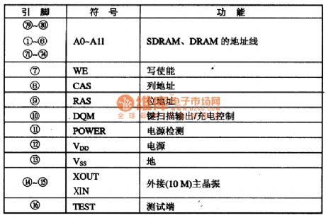
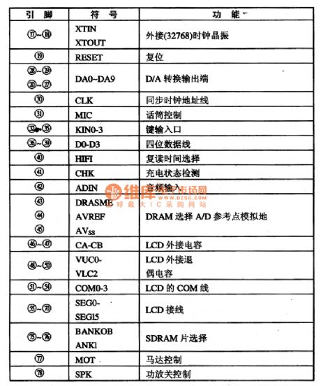
RK609 is the chip microcomputer control integrated circuit that is widely used in TCL, WanLiDa, JinZheng reapter etc.
First,Functions Features
RK609 intergrates CPU, D/A, A/D conversion and LCD display , the input analog signal converts into digital signals via IC , then it is stored in the deposit.
Second,Pins Functions and Data are shown as table 1.RK609 IC pins functions are shown as table 1.
Table 1:RK609 IC Pins Functions (View)
View full Circuit Diagram | Comments | Reading(619)
PT2380 Dolby Directional Logic Circuit and Tone Choice Intergrated Circuit
Published:2011/8/3 7:14:00 Author:Michel | Keyword: Dolby Directional, Logic Circuit, Tone Choice, Intergrated Circuit


The input voltage of PT2380 is 100mV and work power voltage is 12V.Maximum output voltage undistortion is 3 V, noise level is 0.5-0.6 mV.There are 4 kinds of sound output mode in PT2380,namely,Normal/Flat (Flat), Rock,classical (pop) and POPS (communication).
The four tone modeis controlled by input PWL of SW1 and SW2(⑨ and ⑩ feet).Its inside circuit block diagram of intergrated block is shown as picture 1.
Picture 1:Inside Circuit Block Diagram of PT2380 Intergrated Circuit
Second,Pins Functions and DataPT2380 IC adopts 16 feet DIP package structure and its pins function and data are shown as table 1.
(View)
View full Circuit Diagram | Comments | Reading(1755)
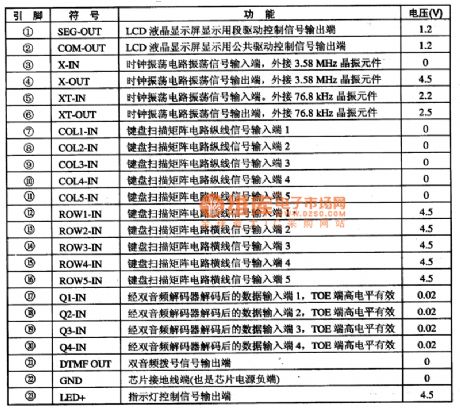
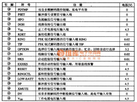
P5346003 Communication Monolithic Microcomputer Integrated Circuit
Published:2011/8/3 7:11:00 Author:Michel | Keyword: Communication, Monolithic Microcomputer, Integrated Circuit
'
P5346003 is a communication single-chip microcomputer integrated circuit and it is widely used in caller id telephone.
First,Functions FeatureS346003 integrated circuit internal basically contains the following functions: FSK circuit frequency shift keying decoder (the decoder is according with BlLL202 and ITU-TV23 standard). LCD drive and control circuit can directly drive LCD screen.A frequency signal generator DTMF, which can achieve a frequency dial-up and the audio signal output controlled by software.The battery is low voltage detection circuit: software control energy saving mode control circuit.
Second,Pins Functions and DataP5346003 integrated circuits uses 30 feet encapsulation, and it is directly sealed in the printed circuit board.It is a kind of four microcomputer and the integrated circuit pins functions are shown as table 1.
Table 1:Microprocessor P5346003 IC Pins and Data (View)
View full Circuit Diagram | Comments | Reading(600)
PCMl710U 2O Double Track DAC Integrated Circuit
Published:2011/8/3 7:09:00 Author:Michel | Keyword: Double Track, DAC Integrated Circuit

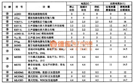
PCMI7I0U is the D/A converter integrated circuits produced by the BB company and it is widely used in VCD, SVCD, DVD, VCD audio D/A transformation.
First,Functions Features
PCMl710U integrated circuit contains eight times sampling digital filter and 4 order noise plastic circuit. It uses many △-∑ structure and level 5 conversion level.They are not sensitive to time setting jitter and power supply fluctuation. There is simulation low pass filter, which can simplify an external circuit of the design.And the failure rate drops greatly.
Second,Pins Functions and Data
PCM1710U integrated circuit uses feet 28 DIP package and its pins functions and data is shown as table 1.
Table 1 :PCMl710U IC Pins Functions and Data (View)
View full Circuit Diagram | Comments | Reading(633)
Battery Charging Circuit for USB
Published:2011/8/3 7:08:00 Author:Michel | Keyword: USB, Battery Charging Circuit

The above picture is battery charging circuit for USB.It is lithium charging circuit with universal serial bus (USB) and the maximum current when it is maximum rating power,5.25V/500mA. In the circuit, LM3622 lithium ion batteries are the controllers.The designing recharging circuit makes USB have the largest power. In normal work situation,the current which is aborbed by the work ability to largest power can not be higher than 5OOmA to satisfy the USB technology index.The biggest charge current is set for 400 mA via limiting resistance R1.And the 100 mA current is provided to charger control circuit etc.During the system starts, LM3525 power switch makes a battery charger and bus remain isolated state.The charging current does not exceed the maximum current provided by the bus. (View)
View full Circuit Diagram | Comments | Reading(1810)
| Pages:571/2234 At 20561562563564565566567568569570571572573574575576577578579580Under 20 |
Circuit Categories
power supply circuit
Amplifier Circuit
Basic Circuit
LED and Light Circuit
Sensor Circuit
Signal Processing
Electrical Equipment Circuit
Control Circuit
Remote Control Circuit
A/D-D/A Converter Circuit
Audio Circuit
Measuring and Test Circuit
Communication Circuit
Computer-Related Circuit
555 Circuit
Automotive Circuit
Repairing Circuit