
Circuit Diagram
Index 564
Production volume automatic counter circuit diagram 3
Published:2011/8/15 1:56:00 Author:Ecco | Keyword: Production volume, automatic counter

The production volume automatic counter circuit is composed of the infrared transmitter, infrared receiver processing circuit, voltage doubling rectifying circuit, control implementation circuit and counting display circuit, and it is shown as the chart. Infrared transmitter circuit consists of the infrared light-emitting diode VL1, resistors R1 ~ R3, diode VD1, capacitors C1 ~ C3 and time-base integrated circuit IC1. Infrared receiver processing circuit consists of the infrared phototransistor V1, transistors V2 ~ W, resistors M ~ R16, capacitors C4 ~ C9, regulator diodes VS1, VS2 and potentiometer RP. Voltage doubling rectifying circuit is composed of the capacitors CIO and C11, diode VD5 and resistors R17 and VD6.
(View)
View full Circuit Diagram | Comments | Reading(980)
Production volume automatic counter circuit diagram 2
Published:2011/8/15 2:08:00 Author:Ecco | Keyword: Production volume, automatic counter
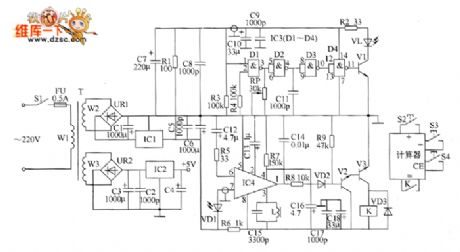
The production volume automatic counter circuit is composed of the power supply circuit, infrared transmitter circuit, infrared receiver amplifier circuit, control implementation circuit and counter control circuit, and it is shown as teh chart. Power supply circuit is composed of the power switch S1, fuse FU, power transformer T, bridge rectifiers UR1 and UR2, three-terminal voltage regulator integrated circuits IC1 and IC2, capacitors C1 ~ C8 and resistor R1. Infrared transmitter circuit consists of NAND gate integrated circuit IC3 (D1 ~ D4), transistor V1, infrared light-emitting diode VL, resistors R2 ~ M, capacitors C9 ~ C11 and potentiometer RP.
(View)
View full Circuit Diagram | Comments | Reading(1496)
Industrial degaussing device circuit diagram
Published:2011/8/10 21:21:00 Author:Ecco | Keyword: Industrial degaussing device
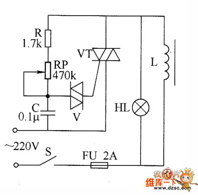
The industrial degaussing device circuit is composed of the fuse FU, thyristor VT, two-way trigger diode V, degaussing coil L, resistor R, potentiometer RP, capacitor C, LED HL, fuse FU and power switch s, and it is shown as the chart. R selects the 1/2W metal film resistor. RP chooses the potentiometer or solid synthetic organic carbon potentiometer with voltage being more than 2W. C uses the CBB capacitor polyester capacitor with the voltage in 250V. V uses the DB3 or 2CTS two-way trigger diode. VT uses the 100V, 10A two-way intergranular tube. HL chooses the 15W, 220V incandescent bulb. S selects the 5A, 220V power switch.
(View)
View full Circuit Diagram | Comments | Reading(2999)
Production volume automatic counter circuit diagram 1
Published:2011/8/15 2:05:00 Author:Ecco | Keyword: Production volume , automatic counter

Infrared transmitter circuit is composed of the capacitance feedback oscillator circuit, 40kHz pulse oscillator and driver circuit, and it is shown as the chart. Capacitance feedback oscillator circuit consists of D1 and D2 which are inside of NAND gate integrated circuit IC1 (D1 ~ D4) and the internal resistors R1 and R2, capacitor C1. 40kHz pulse oscillator circuit consists of IC1's internal D3 and D4 and resistors R3 and R4, capacitor C2. Driver circuit consists of NAND gate integrated circuit IC2 (D5, D6), resistors R5 and R6, transistor V1 and infrared light-emitting diode VL1.
(View)
View full Circuit Diagram | Comments | Reading(1028)
Demagnetizer energy-saving controller circuit diagram
Published:2011/8/11 1:09:00 Author:Ecco | Keyword: Demagnetizer, energy-saving controller

The demagnetizer energy-saving controller circuit is composed of the relay K, transistor V, time-base integrated circuit IC, diode VD, resistors R1, R2, potentiometer RP, capacitors C1, C2, battery GB, limit switch S4 and manual / automatic control switch S1, and other components, and it is shown as the chart. Knife switch Q, start button S3, stop button S2, contactor KM form the original manual for the demagnetizer machine control circuit. R1 and R2 select the 1/4W metal film resistors. RP uses the organic solid potentiometer. VD selects the 2CPl0 or 1N4007 silicon rectifier diodes.
(View)
View full Circuit Diagram | Comments | Reading(2188)
Welding power regulator circuit diagram
Published:2011/8/11 1:05:00 Author:Ecco | Keyword: Welding power regulator

The welding power regulator circuit is composed of the control switch S, thyristor VT, two-way trigger diode V, potentiometer RP, resistors R1 ~ R3 and capacitors C1, C2, and it is shown as the chart. Adjusting the resistance of RP can change the charge rate of C1 to regulate the conduction angle of VT, then it can reach the purpose of adjusting the welding output power. R1 ~ R3 select the 1W metal film resistors. RP chooses the 2W organic solid potentiometer. C1 and C2 select th CBB capacitors with voltage in 630V. V uses the DB3 two-way trigger diode.
(View)
View full Circuit Diagram | Comments | Reading(3878)
Pressure tank air pressure abnormality alarm circuit diagram
Published:2011/8/11 0:58:00 Author:Ecco | Keyword: Pressure tank , air pressure , abnormality alarm

The pressure tank air pressure abnormality detection alarm circuit is composed of the pressure control circuit, LED indication circuit and voice alarm circuit, and it is shown as the chart. The air pressure measurement and control circuit is composed of the power switch S, battery CB, electric contact pressure gauge Q. LED indicator circuit is composed of the green LED VL1, red light-emitting diode VL2 and resistors R1, R2. R1 ~ R3 select the t/4W metal film resistors or a carbon film resistors. C1 select the electrolytic capacitor with voltage in 16V: C2 uses the high-frequency ceramic capacitor. VD1 and VD2 use 1N4001 or 1N4007 type silicon rectifier diodes.
(View)
View full Circuit Diagram | Comments | Reading(1914)
Bearing fault detector circuit diagram 2
Published:2011/8/10 22:23:00 Author:Ecco | Keyword: Bearing fault detector

The bearing fault detection circuit is composed of the bearing detection sensors, signal processing circuit and sound and light circuit, and it is shown as the chart. Signal processing circuit consists of the input socket XS, voice integrated circuit IC1, capacitors C1 ~ C3, resistors R1, R2 and potentiometer RP. Sound and light is composed of the transistors V1, V2, LEDs VL1, VL2, audio power amplifier integrated circuit IC2, resistors R3, R4, capacitor C4, diodes VD1, VD2, and speaker BL. R1 ~ M select the 1/4W or 1/8W metal film resistors. RP uses the small synthetic membrane potentiometer or variable resistor.
(View)
View full Circuit Diagram | Comments | Reading(1595)
Cumulative timer circuit diagram
Published:2011/8/10 22:13:00 Author:Ecco | Keyword: Cumulative timer

The cumulative timer circuit consists of resistor R1 and spreadsheet internal crystal oscillator BC, and it is shown as the chart. R1 and R2 choose the metal film resistors: R3 ~ R5 select the 1/8W metal film resistors. C select the aluminum electrolytic capacitor with voltage being above 10V. VD1 ~ VD4 use the 1N4007 silicon rectifier diodes; VD5 uses the 1N4l48 or 2CK44A silicon switching diode. V1 and V2 use S9013 or 3DG6 silicon NPN transistors. Digital watchesse use the multi-function LCD digital watches.
(View)
View full Circuit Diagram | Comments | Reading(1643)
TEA2161 switching power thick film IC diagram
Published:2011/8/15 21:36:00 Author:Ecco | Keyword: switching power, thick film IC

TEA2261 is the switching power thick film integrated circuit produced by Thomson, and it is widely used in Samsung series (such as C56226Z, C57230Z), Changhong CNS movement (eg, N2516, N2918), Feiyue FY703, Panda 2528,2928, C74P1, Venus C6418, etc. TV. TEA2261 IC's pin function and data are listed in Table 1-1.
(View)
View full Circuit Diagram | Comments | Reading(994)
TEA2164 switching power thick film IC diagram
Published:2011/8/15 21:34:00 Author:Ecco | Keyword: switching power , thick film IC

TEA2164 is the switching power thick film integrated circuit produced by Thomson, and it is widely used in Toshiba XH series (such as 2500XH, 2506XH, 2806XH), the West Lake series (such as C2918) of color television. 1. Features and functionsTEA2164 integrated circuit contains the oscillator circuit, starting circuit, driving pulse output circuit, delay circuit, synchronous control circuit, and other auxiliary functions circuit. 2. pin functions and data TEA2164 IC uses 16-pin double row package, and the pin function and data are listed in Table 1-1.
(View)
View full Circuit Diagram | Comments | Reading(734)
TEAl062 Calling integrated circuit diagram
Published:2011/8/15 21:30:00 Author:Ecco | Keyword: Calling integrated circuit

TEA1062 series of dedicated calling integrated circuits are widely used in telephone circuits. TEA1062 integrated circuit has the electrical chanting machine call and required line interface for dialing and call switching, and it is ideal for a wide range of calling integrated circuits. It uses 16-pin dual in-line package, and the integrated circuit pin functions and data are listed in Table 1-1.
(View)
View full Circuit Diagram | Comments | Reading(598)
TEAl021 microcomputer dialing IC diagram
Published:2011/8/15 21:26:00 Author:Ecco | Keyword: microcomputer dialing IC
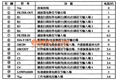
TEA1021 series of microcomputer dialing integrated circuit is widely used in telephone communication. 1. Features and funcyionsTSA1O21 IC contains keyboard switch signal encoding and decoding circuit, dial-up signal processing circuit. 2. pin functions and data TEA1021 integrated circuit'spin functions and data are listed in Table 1-1.
(View)
View full Circuit Diagram | Comments | Reading(822)
Remote control electric hoist control circuit diagram 2
Published:2011/8/15 22:07:00 Author:Ecco | Keyword: Remote control, electric hoist control
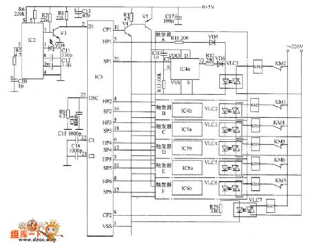
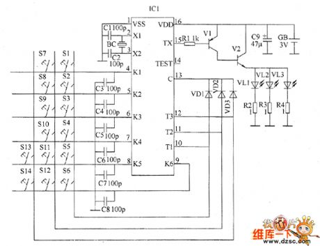
The remote control electric hoist control circuit consists of the infrared transmitter and infrared receiver control circuit. Infrared transmitter circuit is composed of the infrared emission coding circuit and peripheral components of integrated circuit ICI, and it is shown in Figure 1. Control buttons S1 ~ S4, diodes VD1 ~ VD3, capacitors C3 ~ C8 and IC1's pin 4 to 13 internal circuit form the keying input circuit; capacitors C1 and C2, quartz crystal oscillator BC and IC1'S pin 2,3 internal circuit form the oscillator circuit; resistors RI ~ M, transistors VI and infrared light-emitting diodes VL1 ~ VL3 and IC1's pin 15 internal circuit form the infrared driver circuit.
(View)
View full Circuit Diagram | Comments | Reading(2917)
Temperature controller circuit diagram 6
Published:2011/8/15 21:44:00 Author:Ecco | Keyword: Temperature controller

The temperature controller circuit is composed of the power supply circuit, temperature detection control circuit, LED indication circuit and heater control circuit, and it is shown as the chart. Power supply circuit is composed of the power transformer T, rectifier diodes VD1 ~ VD4, three-terminal voltage regulator integrated circuit IC5 and filter capacitor C1. Temperature detection control circuit is composed of the temperature sensor integrated circuit IC1, temperature control selector switch S, three-terminal voltage regulator integrated circuit IC2 and the resistors R1 ~ R6. LED temperature indicator circuit is composed of the voltage reference integrated circuit IC3, LED display driver integrated circuit IC4, resistors R8 ~ R13 and LEDs VL1 ~ VL10.
(View)
View full Circuit Diagram | Comments | Reading(1600)
Liquid level controller circuit diagram 2
Published:2011/8/15 22:14:00 Author:Ecco | Keyword: Liquid level controller

The liquid level controller circuit consists of the power supply circuit and level detection control circuit, and it is shown as the chart. Power supply circuit consists of the power transformer T, bridge rectifier UR and filter capacitors C1, C2. Liquid level detection control circuit consists of electrodes A ~ C, four NAND gate IC IC (D1 ~ D4), transistor V, resistors R1 ~ R3, relay K and diode VD. R1 ~ R3 select the 1/4W carbon film resistors or metal film resistors. C1 selects the monolithic capacitor with voltage in 63V: C2 selects the aluminum electrolytic capacitor with voltage in 25V.
(View)
View full Circuit Diagram | Comments | Reading(1687)
Liquid level controller circuit diagram 1
Published:2011/8/15 22:10:00 Author:Ecco | Keyword: Liquid level controller

The liquid level controller circuit consists of the power supply circuit and level detection control circuit, and it is shown as the chart. Power supply circuit consists of the power switch S1, power transformer T, bridge rectifiers UR1, UR2 and filter capacitors C1, C2. Liquid level detection control circuit is composed of the test electrodes a ~ c, control buttons S2, S3, resistors R1 ~ M, transistors V1, V2, LEDs VL1, VL2, relay K, and AC contactor KM, diode VD. R1 ~ R4 select the 1/4W metal film resistors or carbon film resistors.
(View)
View full Circuit Diagram | Comments | Reading(2511)
Intermittent controller circuit diagram 3
Published:2011/8/15 1:36:00 Author:Ecco | Keyword: Intermittent controller

The intermittent controller circuit is composed of the power supply circuit, timing control circuit and control implementation circuit, and it is shown as the chart. The power supply circuit is composed of the step-down capacitor C1, resistors R1, R5, rectifier diodes VD1 ~ VD4, voltage regulator diode VS, power indicator LED VL1 and filter capacitor C2. Timing control circuit consists of the time-base integrated circuit IC, resistors R2 ~ R4, capacitors C3, C4, potentiometers RP1, RP2, diodes VD5, VD6 and light-emitting diode VL2. Control implementation circuit is composed of the diode VD7, AC contactor KM and relay K.
(View)
View full Circuit Diagram | Comments | Reading(565)
Intermittent controller circuit diagram 2
Published:2011/8/15 1:31:00 Author:Ecco | Keyword: intermittent controller

The intermittent controller circuit is composed of the power supply circuit, timing control circuit and control implementation circuit, and it is shown as the chart. Power supply circuit is composed of the fuse FU, power transformer T, bridge rectifier UR, filter capacitor C3, three-terminal voltage regulator integrated circuit IC2, current limiting resistor R1 and the power indicator LED VL1. Timing control circuit consists of the time-base integrated circuit IC1, potentiometers RP1 and RP2, resistor R2, working indication LED VL2 and capacitors C1, C2. Control implementation circuit consists of the relay K, AC contactor KM and diode VD.
(View)
View full Circuit Diagram | Comments | Reading(729)
MAX4295, MAX4297 high-efficient Class-D audio amplifier circuit diagram
Published:2011/8/14 21:38:00 Author:Ecco | Keyword: high-efficient, Class-D audio amplifier
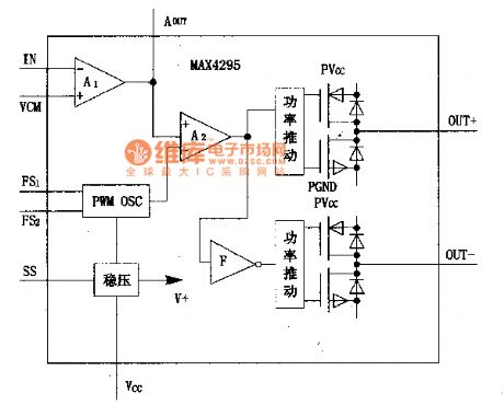
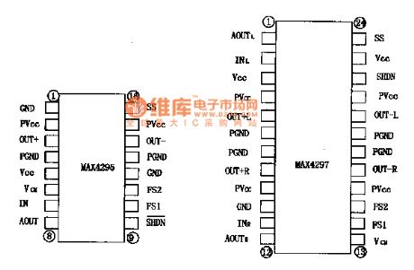
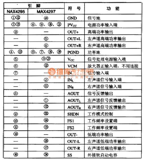
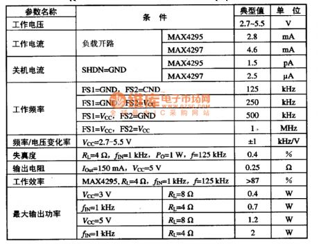
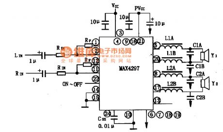
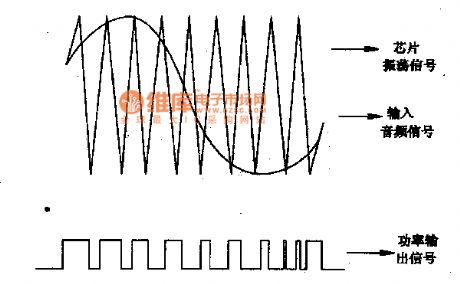
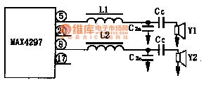
MAX4295 and MAX4297 are the latest switching (D class) audio amplifiers produced by U.S. MAXIM (Maxim), and it is widely used in pronunciation electronic products, such as walkman notebook computers, music cards, mobile phones and other battery-powered electrical products, and you can maximize battery life. 1. The internal block diagram and pin functions The MAX4295 is a mono amplifier, MAX4295 is the dual-channel amplifier. It is composed of the voltage reference, input buffer amplifier, oscillator, PWM modulator, power driver and MOSFET and other components.
(View)
View full Circuit Diagram | Comments | Reading(1280)
| Pages:564/2234 At 20561562563564565566567568569570571572573574575576577578579580Under 20 |
Circuit Categories
power supply circuit
Amplifier Circuit
Basic Circuit
LED and Light Circuit
Sensor Circuit
Signal Processing
Electrical Equipment Circuit
Control Circuit
Remote Control Circuit
A/D-D/A Converter Circuit
Audio Circuit
Measuring and Test Circuit
Communication Circuit
Computer-Related Circuit
555 Circuit
Automotive Circuit
Repairing Circuit