
Circuit Diagram
Index 565
Fish farming oxygen increasing controller 4
Published:2011/8/9 22:08:00 Author:Ecco | Keyword: Fish farming, oxygen increasing controller

The fish farming oxygen increasing controller circuit is composed of the power supply circuit and control circuit, and it is shown in Figure 4-21. Power supply circuit is composed of the power switch S, power transformer T, rectifier diode VDl-VD4 and filter capacitor Cl. Control circuit consists of transistors Vl, V2, relays Kl, K2, resistors Rl-R4, capacitors C2, C3 and diodes VD5, VD6. RI-R4 select the 1/4W carbon film resistors or metal film resistors. Cl uses the aluminum electrolytic capacitor with voltage in 35V; C2 and C3 select the aluminum electrolytic capacitors with voltage in 25V. VDI-VD6 use 1N4007 silicon rectifier diodes. Vl and V2 choose C8050 or S8050 silicon NPN transistors.
(View)
View full Circuit Diagram | Comments | Reading(571)
Fish farming oxygen increasing controller 3
Published:2011/8/9 22:04:00 Author:Ecco | Keyword: Fish farming, oxygen increasing controller

The fish farming oxygen increasing circuit is composed of the power supply circuit, clock-control timing circuit and intermittent control circuit, and it is shown in Figure 4-20. Power supply circuit consists of the power button S0, power transformer T, bridge rectifier UR and filter capacitor C1. Clock-control timing circuit is composed of clock-control board circuit ICl, resistors Rl-R4, diodes VDl-VD3, time set buttons S1-S3, SCR VT, relay Kl and capacitor C2. Intermittent control circuit is composed of the time-base integrated circuit IC2, resistors R5, R6, potentiometers RPl, RP2, capacitors C3, C4, diodes VD4-VD6 and relay K2.
(View)
View full Circuit Diagram | Comments | Reading(587)
High-voltage amplifier circuit diagram for piezoelectric ceramic element
Published:2011/8/14 22:22:00 Author:Ecco | Keyword: High-voltage amplifier, piezoelectric ceramic element
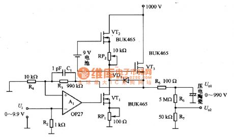
Figure 1 shows the high-voltage amplifier for piezoelectric ceramic element. Piezoelectric ceramic element is an excellent location converter, which is widely used in micrometer and so on. Piezoelectric ceramic element has the maximum elongation in 2OkV / magnitude electric field with typical value in 0.1%, so here needs to use high-voltage amplifier. This is a simple, low-cost 1000V high-voltage amplifier. Piezoelectric ceramic element is used as the amplifier load. High-voltage amplifier consists of three high-voltage MOSFET (BUK465) and a low-noise operational amplifier (0P27) and so on.
(View)
View full Circuit Diagram | Comments | Reading(6460)
Fish farming oxygen increasing controller 2
Published:2011/8/9 21:54:00 Author:Ecco | Keyword: Fish farming , oxygen increasing controller

The fish farming oxygen increasing circuit is composed of the power supply circuit, timing control circuit and control implementation circuit and working status indication circuit, and it is shown in Figure 4-19. Power supply circuit consists of the fuse FU, power transformer T, rectifier diodes VD6-VDg and filter capacitor Cl. Timing controller circuit consists of the timer integrated circuit IC, resistors Rl-R3, potentiometer RP, capacitors C2, C3, diodes VDl-VD4 and control switches Sl-S4. Control implementation circuit consists of the resistor R4, transistor Vl, diodes VD5, VDlO, thyristor VT and the relay K.
(View)
View full Circuit Diagram | Comments | Reading(555)
Fish farming oxygen increasing controller 1
Published:2011/8/9 21:51:00 Author:Ecco | Keyword: Fish farming , oxygen increasing controller

The fish farming oxygen increasing circuit is composed of the power supply circuit and time control circuit, and it is shown in Figure 4-18. Power supply circuit consists of the power transformer T, rectifier diodes VDl-VD4, three-terminal voltage regulator integrated circuit ICl, filter capacitors Cl, C2, current limiting resistor Rl, and power indicator light-emitting diode VL. Timing control circuit consists of resistors R2-R4, potentiometer RP, diodes VD5-VD7, control switch S, capacitors C3, C4, transistors V, time-base integrated circuit IC2 and relay K. Rl-R4 select the 1/4W metal film resistors or carbon film resistors. RP uses the organic solid potentiometer.
(View)
View full Circuit Diagram | Comments | Reading(589)
Animal litter teller device 2
Published:2011/8/10 3:36:00 Author:Ecco | Keyword: Animal litter teller
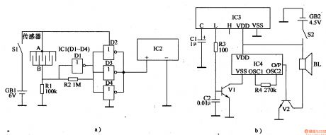
The animal litter teller circuit is composed of the detection signal wireless transmitter circuit, wireless receiver alarm circuit, and it is shown in Figure 4-17. Detection signal wireless transmitter circuit is composed of the battery GBl, power switch Sl, sensors, resistors Rl, R2, NOT gate integrated circuit ICl (Dl-D4) and wireless remote control transmitter integrated circuit IC2. Wireless receiver alarm circuit is composed of the wireless remote control integrated circuit IC3, resistors R3, R4, capacitors Cl, C2, transistors Vl, V2, alarm sound integrated circuit IC4, battery GB2, power switch S2 and the speaker BL.
(View)
View full Circuit Diagram | Comments | Reading(884)
M54543L loading motor driver IC diagram
Published:2011/8/14 22:17:00 Author:Ecco | Keyword: loading motor, driver IC


M54543L is the loading motor driver IC manufactured by Japan's Mitsubishi, and it is widely used in various camcorders. M54543L IC uses 9-pin single package, and the integrated circuit pin functions and data are listed in Table 1-1, the typical application circuit of manifold is shown in Figure 1.
(View)
View full Circuit Diagram | Comments | Reading(1027)
Animal litter teller device 1
Published:2011/8/10 3:32:00 Author:Ecco | Keyword: Animal litter teller

The animal litter teller circuit is composed of the detection control circuit and alarm signal transmission circuit, and it is shown in Figure 4-16. Detection control circuit consists of comb detection sensor, resistors Rl, R2, capacitors Cl-C3, light-emitting diode V1 and transistor VL. Alarm signal transmission circuit consists of the audio integrated circuit IC, capacitors C4-ClO, resistors R3-R6, transistors V2, V3, antenna W and inductor L. RI-R6 select the 1/4W metal film resistors or carbon film resistors. C2, C5, C8 and C9 use the monolithic capacitors.
(View)
View full Circuit Diagram | Comments | Reading(959)
Chicks hatched informing device 3
Published:2011/8/11 20:45:00 Author:Ecco | Keyword: Chicks , hatched informing device

The chicks hatched informing device circuit is composed of the sonic circuit, delay circuit and alarm circuit and other components, and it is shown in Figure 4-15. Sonic circuit consists of the microphone BM, NOT gate circuits D1, D2 which are inside of NOT gate IC (Dl-D4), resistors Rl-R4, R6, potentiometer RP and capacitors Cl, C2 and so on. Delay circuit consists of resistor R5, capacitor C3, diode VDl and NOT gate circuits D3, D4 which are inside of NOT gate IC. Alarm circuit consists of the relay K, diode VD2, transistor V, resistor R7 and buzzer HA. Rl-R7 select the 1/4W metal film resistors or carbon film resistors. RP uses the small synthetic membrane potentiometer or variable resistor.
(View)
View full Circuit Diagram | Comments | Reading(865)
Chicks hatched informing device 2
Published:2011/8/11 20:36:00 Author:Ecco | Keyword: Chicks , hatched informing device
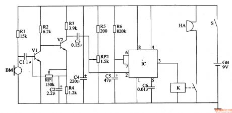
The chicks hatched informing device circuit is composed of the sonic amplifier circuit, monostable delay circuit and alarm circuit, and it is shown in Figure 4-14. Sonic amplifier circuit consists of the microphone amplifier BM, resistors Rl-R4, capacitors Cl, C2, potentiometer RPl and transistors Vl, V2. Monostable delay circuit consists of the time-base lC, resistors R5, R6, potentiometer RP2 and capacitors C3-C5. Alarm circuit consists of the relay K and buzzer HA. Rl-R6 select the 1/4W metal film resistors or carbon film resistors. RPl and RP2 use the small solid potentiometer or WSW solid variable resistor.
(View)
View full Circuit Diagram | Comments | Reading(893)
M52470AP audio- video switch IC diagram
Published:2011/8/14 22:13:00 Author:Ecco | Keyword: audio- video switching IC

M52470AP is the audio-video switching integrated circuit produced by Japanese Mitsubishi company, and it is widely used in TV Changhong CN-l5 movement and other brands of big screen color TV. M52470 IC contains 4-way inputs and 3-way switching electronic switch circuits. In the movements of CN-l5 color TV, the integrated circuit pin functions and data are listed in Table 1.
(View)
View full Circuit Diagram | Comments | Reading(1141)
Chicks hatched informing device 1
Published:2011/8/11 20:32:00 Author:Ecco | Keyword: Chicks , hatched informing device
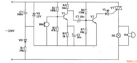
The chicks hatched informing device circuit is composed of the power supply circuit, audio amplifier and sound and light alarm circuit, and it is shown in Figure 4-13. Power supply circuit consists of the current limiting resistor Rl, rectifier diode VD, voltage regulator diode VS and filter capacitor CI. Audio amplifier circuit consists of the microphone BM, transistors Vl, V2, resistors Rl-R7 and capacitors C2, C3. Sound and light alarm circuit consists of the thyristor VT, LED VL, bell HA and lights HL. Rl uses the 3W metal film resistor; R2-R7 select the 1/4W carbon film resistors. VD uses the 1N4007 silicon rectifier diode.
(View)
View full Circuit Diagram | Comments | Reading(831)
M51327P electronic switch IC diagram
Published:2011/8/14 21:47:00 Author:Ecco | Keyword: electronic switch IC


M51327P is the electronic switch integrated circuit produced by Japanese Mitsubishi company, and it is commonly used in video, audio and other systems used for signal switching. M51327P is used for TW / AV switch, and its integrated circuit pin functions and data are listed in Table 1.
(View)
View full Circuit Diagram | Comments | Reading(571)
Chicken male and female discriminator 2
Published:2011/8/11 20:23:00 Author:Ecco | Keyword: Chicken discriminator, male and female

The chicken male and female discriminator circuit is composed of the pickup amplifier circuit, frequency selection circuit and LED driver circuit, and it is shown in Figure 4-12. Pickup amplifier circuit consists of the microphone BM, transistor Vl, resistors Rl-R5 and capacitor Cl. Frequency selection circuit consists of the inductors Ll, K2, capacitors C3, C4 and switch Sl. Ll and C3 form the 5.2kHz frequency selection loop, then L2 and C4 form the 4.8kHz frequency selection loop. LED driver circuit is composed of the capacitor C2, resistors R6, R7, transistor V2 and light emitting diode VL. Rl-R7 select the 1/8W metal film resistors or carbon film resistors.
(View)
View full Circuit Diagram | Comments | Reading(1487)
Mitsubishi Pajero puddle jumper schematic outline diagram
Published:2011/8/14 22:08:00 Author:Ecco | Keyword: Mitsubishi Pajero , puddle jumper , schematic outline diagram

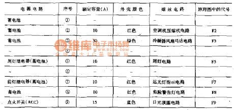
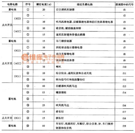
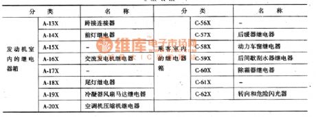
Pajero puddle jumper circuit outline is shown in Figure 1 to Figure 4, and people should pay attention to distinguish between the fusible wire, dedicated fuse and multi-fuse fuse and their different capacities, different location when they detect it.
(View)
View full Circuit Diagram | Comments | Reading(717)
Chicken male and female discriminator 1
Published:2011/8/11 22:12:00 Author:Ecco | Keyword: Chicken discriminator, male and female discriminator

The chicken male and female discriminator circuit is composed of the audio detection circuit, active band-pass filter and LED display circuit, and it is shown in Figure 4-11. Audio detection circuit consists of piezoelectric ceramic BC and resistor Rl, R2. Active band-pass filter is composed of the operation integrated circuit IC and resistors R3-R5, capacitors Cl-C3, potentiometer RP. LED display circuit is composed of the capacitor C4, resistor R6 and light-emitting diode VL. Rl-R6 select the 1/8W precision metal film resistors(error is ± 1%). RP uses the small synthetic film variable resistor. Cl-C3 chooses the high-frequency ceramic capacitors, C4 uses the monolithic capacitor.
(View)
View full Circuit Diagram | Comments | Reading(2038)
Chicken farm automatic filling light 3
Published:2011/8/11 22:20:00 Author:Ecco | Keyword: Chicken farm, automatic filling light

The chicken farm automatic filling light circuit is composed of the power supply circuit, light control circuit, timing circuit and control implementation circuit, and it is shown in Figure 4-10. Power supply circuit is composed of the power switch S, power transformer T, rectifier diodes VD1-VD4, filter capacitors Cl, C2, and three-terminal voltage regulator integrated circuit ICI. Light control circuit is composed of the photosensitive resistor RG, potentiometer RPl, resistor Rl, capacitor C3 and the time-base integrated circuit IC2. Timing circuit is composed of the timer integrated circuit IC3, resistors R2, R7, potentiometer RP2, capacitor C5 and diode VD5. Rl-R7 select the 1/4W metal film resistors or carbon film resistors.
(View)
View full Circuit Diagram | Comments | Reading(904)
Chicken farm automatic filling light 2
Published:2011/8/11 22:24:00 Author:Ecco | Keyword: Chicken farm , automatic filling light

The chicken farm automatic filling light circuit is composed of the power supply circuit, metering circuit and dimming circuit, and it is shown in Figure 4-9. Power supply circuit is composed of the power switch S, power transformer T, rectifier diodes VDl-VD4, filter capacitors C2, C3, three-terminal voltage regulator integrated circuit IC, current-limiting resistor R4 and power indicator light-emitting diode VL. Metering circuit is composed of the photosensitive resistor RC, potentiometers RPl, RP2, resistors Rl, R2 and transistors Vl-V3. Dimming circuit consists of transistor V3, single-junction transistor VU, thyristor VT, resistors R2, R3, capacitor Cl and filling light EL.
(View)
View full Circuit Diagram | Comments | Reading(1614)
Chicken farm automatic filling light 1
Published:2011/8/10 2:29:00 Author:Ecco | Keyword: Chicken farm, automatic filling light

The chicken farm automatic filling light is composed of the power supply circuit, light control circuit, driver control circuit and lighting circuit, and it is shown as the Figure 4-8. Power supply circuit consists of the power switch S, fuse FU, power transformer T, rectifier diodes VDl-VD8, filter capacitors Cl-C4 and three-terminal voltage regulator integrated circuits ICl, lC2. Light control circuit by the photosensitive resistor RG, resistors Rl-R3, capacitor C5, C6 and time-base integrated circuit IC3. Drive control circuit consists of the resistors R4-R9, operational amplifier integrated circuit IC4, diode VDg, transistor V and relay Kl.
(View)
View full Circuit Diagram | Comments | Reading(1340)
The application circuit diagram of thermal conductivity gas sensor with RTD
Published:2011/8/14 22:01:00 Author:Ecco | Keyword: application circuit , thermal conductivity , gas sensor , RTD

The principle of the sensor: when it is in high temperature (200 to 800 ℃), the temperature of the sensor changes with the gas thermal conductivity, then the resistance of platinum resistor wire is detected. In the circuit, RA and RB are the platinum resistor wires, which are respectively used as detection device and temperature compensation element. Detection devices work according to temperature changes, so the bridge voltage requires a high stability. Compared to air, the hydrogen has larger thermal conductivity, which is easy to measure, therefore, the voltage stability of bridge is 0.1%.
(View)
View full Circuit Diagram | Comments | Reading(2183)
| Pages:565/2234 At 20561562563564565566567568569570571572573574575576577578579580Under 20 |
Circuit Categories
power supply circuit
Amplifier Circuit
Basic Circuit
LED and Light Circuit
Sensor Circuit
Signal Processing
Electrical Equipment Circuit
Control Circuit
Remote Control Circuit
A/D-D/A Converter Circuit
Audio Circuit
Measuring and Test Circuit
Communication Circuit
Computer-Related Circuit
555 Circuit
Automotive Circuit
Repairing Circuit