
Circuit Diagram
Index 562
The Fukang car ABS computer control circuit
Published:2011/8/11 7:31:00 Author:Borg | Keyword: Fukang, ABS, computer control circuit

The Fukang car ABS computer control circuit (View)
View full Circuit Diagram | Comments | Reading(742)
The Fukang car ABS control circuit
Published:2011/8/11 8:10:00 Author:Borg | Keyword: Fukang, control circuit

The Fukang car ABS control circuit (View)
View full Circuit Diagram | Comments | Reading(639)
The Fukang car AL4 auto transmission electric control system circuit
Published:2011/8/11 8:12:00 Author:Borg | Keyword: Fukang, auto transmission, control system

The Fukang car AL4 auto transmission electric control system circuit (View)
View full Circuit Diagram | Comments | Reading(2027)
The Fukang car engine oil injection control system circuit
Published:2011/8/11 8:14:00 Author:Borg | Keyword: Fukang, engine oil, control system

The Fukang car engine oil injection control system circuit (View)
View full Circuit Diagram | Comments | Reading(909)
The simple triangular wave switching sine wave circuit
Published:2011/8/11 8:15:00 Author:Borg | Keyword: triangular wave, sine wave

The simple triangular wave switching sine wave circuit is shown as above.
(View)
View full Circuit Diagram | Comments | Reading(2224)
The NISSAN new Teana stereo (with GPS) circuit (3)
Published:2011/8/11 7:23:00 Author:Borg | Keyword: NISSAN, Teana, stereo
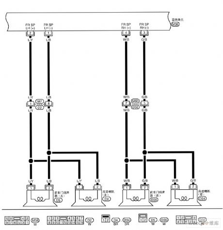
The NISSAN new Teana stereo (with GPS) circuit (3) (View)
View full Circuit Diagram | Comments | Reading(869)
The NISSAN new Teana stereo (with GPS) circuit (2)
Published:2011/8/11 7:24:00 Author:Borg | Keyword: NISSAN, new Teana, stereo

The NISSAN new Teana stereo (with GPS) circuit (2) (View)
View full Circuit Diagram | Comments | Reading(800)
The NISSAN new Teana stereo (with GPS) circuit
Published:2011/8/11 3:45:00 Author:Borg | Keyword: NISSAN, Teana, GPS
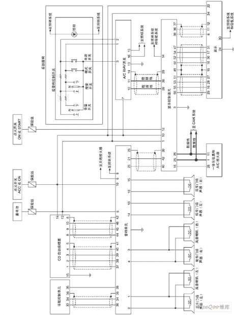
The NISSAN new Teana stereo (with GPS) circuit (View)
View full Circuit Diagram | Comments | Reading(1043)
The stereo toy car circuit
Published:2011/8/15 21:05:00 Author: | Keyword: stereo, toy car
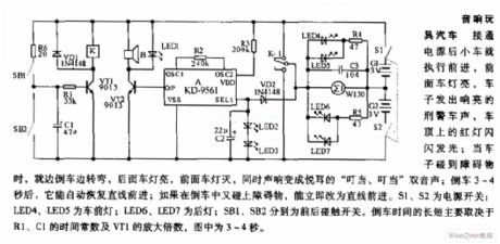
The stereo toy car circuit After the power is on, the toy car is running forward, the front light is glowing, the car is making the police car sound, and the red light on the top of the car is flashing; when the car is touching the obstacle, it is making a turn and backing off, the rear light is glowing, the front light is put off, at the same time, the sound is changed into sweet ding-dong, ding-dong dual sound. After it is backing off for 3~4s, it will run forward again automatically; if it touches the obstacle while backing off, it will change the route and run forward immediately.
(View)
View full Circuit Diagram | Comments | Reading(948)
The light chasing beetle circuit
Published:2011/8/15 21:16:00 Author: | Keyword: light chasing, beetle
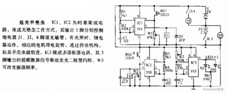
The light chasing beetle circuit Both IC1 and IC2 are the time-based integrated circuits, and they are fixed in the non-steady working state. The 3 pin output by it control relay J1, J2 and J3 respectively, the 4-pin is linked with the LST. When there is light, the relay is working, and the relative motor is running, with the help of the driving gear, the toy beetle is going forward. IC3 is a multi-resonance oscillator circuit, whose 3-pin outputs the low oscillating signal which drives the LED to flash, W3 can change the oscillating frequency.
(View)
View full Circuit Diagram | Comments | Reading(720)
The NISSAN new Teana stereo aerial circuit
Published:2011/8/11 4:04:00 Author:Borg | Keyword: NISSAN, new Teana, stereo aerial

The NISSAN new Teana stereo aerial circuit (View)
View full Circuit Diagram | Comments | Reading(814)
The NISSAN new Teana fault diagnosis circuit
Published:2011/8/11 7:28:00 Author:Borg | Keyword: NISSAN, Teana, fault diagnosis circuit

The NISSAN new Teana fault diagnosis circuit (View)
View full Circuit Diagram | Comments | Reading(897)
The NISSAN new Teana A/T gear-shifting lock system circuit
Published:2011/8/11 7:30:00 Author:Borg | Keyword: NISSAN, Teana, gear-shifting lock system

The NISSAN new Teana A/T gear-shifting lock system circuit (View)
View full Circuit Diagram | Comments | Reading(871)
The NISSAN new Teana speed sensor A/T circuit
Published:2011/8/11 7:33:00 Author:Borg | Keyword: NISSAN, Teana, speed sensor
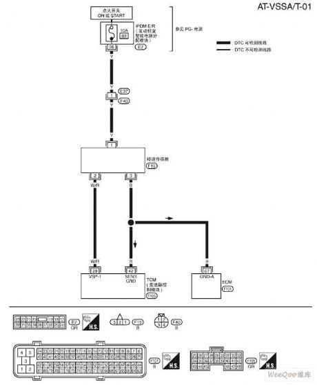
The NISSAN new Teana speed sensor A/T circuit (View)
View full Circuit Diagram | Comments | Reading(864)
The NISSAN new Teana speed sensor MTR circuit
Published:2011/8/11 7:34:00 Author:Borg | Keyword: NISSAN, Teana, speed sensor, MTR
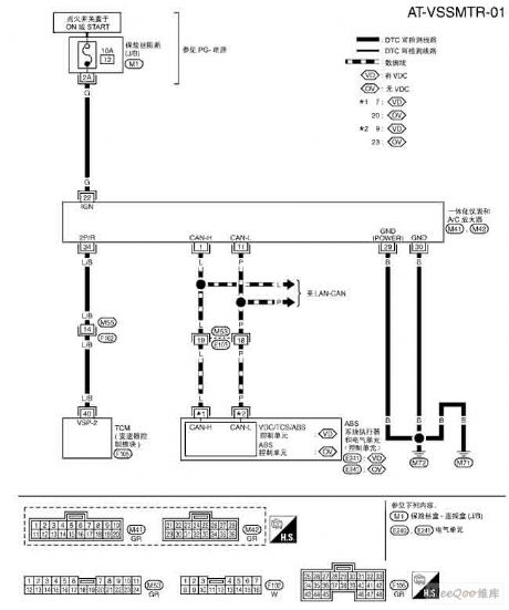
The NISSAN new Teana speed sensor MTR circuit (View)
View full Circuit Diagram | Comments | Reading(953)
The NISSAN new Teana accerating pad position(APP) circut
Published:2011/8/11 7:37:00 Author:Borg | Keyword: NISSAN, Teana, accerating pad position, APP
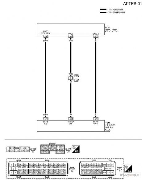
The NISSAN new Teana accerating pad position(APP) circut (View)
View full Circuit Diagram | Comments | Reading(854)
MAX639 Basic Application Circuit
Published:2011/8/11 6:34:00 Author:Robert | Keyword: Basic, Application
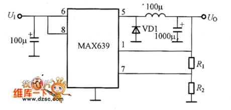
The picture shows the MAX639 basic application circuit. (View)
View full Circuit Diagram | Comments | Reading(994)
MAX730 Series Integrated Voltage Regulator Internal Equivalent Circuit
Published:2011/8/11 6:30:00 Author:Robert | Keyword: Series, Integrated, Voltage, Regulator, Internal, Equivalent
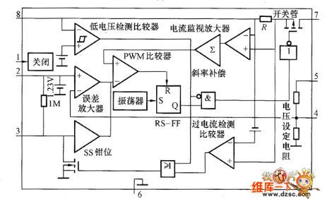

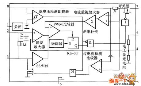
The MAX730 series integrated voltage regulator internal equivalent circuit is shown in the picture. (View)
View full Circuit Diagram | Comments | Reading(1089)
MAX730 Basic Application Circuit
Published:2011/8/11 6:27:00 Author:Robert | Keyword: Basic, Application

The MAX730 basic application circuit is shown in the picture. (View)
View full Circuit Diagram | Comments | Reading(783)
LT1766 Application Circuit
Published:2011/8/12 18:22:00 Author:Robert | Keyword: Application

The picture (a) shows the LT1766 internal equivalent circuit. In the chip it has the 200kHz oscillator, driving circuit, switch tube and other all function circuits which are needed by the buck voltage converter. The oscillation frequency is 20.0Hz and the internal-chip power transistor VT1's peak current is 1.5A. The picture (b) shows the buck voltage DC-DC converter composed of LT1766. It would convert the 5.5~60V input voltage to the 5V/1A output. This circuit's feature is wide input voltage range which is from 5.5 to 60V. It can be used in high-voltage car electronic devices, battery charger, distributed power supply and so on. (View)
View full Circuit Diagram | Comments | Reading(875)
| Pages:562/2234 At 20561562563564565566567568569570571572573574575576577578579580Under 20 |
Circuit Categories
power supply circuit
Amplifier Circuit
Basic Circuit
LED and Light Circuit
Sensor Circuit
Signal Processing
Electrical Equipment Circuit
Control Circuit
Remote Control Circuit
A/D-D/A Converter Circuit
Audio Circuit
Measuring and Test Circuit
Communication Circuit
Computer-Related Circuit
555 Circuit
Automotive Circuit
Repairing Circuit