
Circuit Diagram
Index 563
LT1109/LT1109A Internal Equivalent Circuit And Application Circuit
Published:2011/8/13 21:50:00 Author:Robert | Keyword: Internal, Equivalent, Application
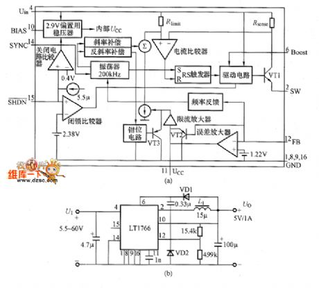
The LT1109/LT1109A is low-power-consumption DC-DC convertor. Its output voltage has fixed three types which are 5V, 12V and adjustable output voltage. Its current consumption is maximum 550pA. For the 5V fixed type its output current is 100mA. For 12V fixed output current it is 60mA. It can control the logic voltage level to close the ports to make the power stop working. It uses 8-pin SOP, DIP and 3-pin T092 (only LT1109) and other packages.
The LT1109/LT1109A internal equivalent circuit diagram and aplication circuit is shown in the picture. The chip has internal 1.25V reference voltage generator and comparator. (View)
View full Circuit Diagram | Comments | Reading(998)
Voice switching and amplifier schematic diagram
Published:2011/8/11 1:43:00 Author:Ecco | Keyword: Voice switching , amplifier

View full Circuit Diagram | Comments | Reading(798)
25W electronic neon circuit diagran
Published:2011/8/11 22:25:00 Author:Ecco | Keyword: 25W electronic neon

Operating frequency is110KHz; Output voltage is2500V; Input AC 220V; LED tube length is 2 m.
(View)
View full Circuit Diagram | Comments | Reading(2538)
Typical application circuit of HFC55 audio control IC
Published:2011/8/8 20:43:00 Author:Ecco | Keyword: Typical application circuit , audio control IC

This start-stop control end S of the device is carried by high level, the external end is connected to a pairof groundswitch K. Each time to press it, the circuit can complete the start or stop conversion.
(View)
View full Circuit Diagram | Comments | Reading(587)
BA2101 touching stepping dimmer circuit
Published:2011/8/8 20:47:00 Author:Ecco | Keyword: touching stepping dimmer

The touching stepping dimmer circuit shown as the chart uses BA2101 dimming ASIC, and it is very suitable for lamp dimming. Touching the electrode M can make the brightness of E lamp change in the cycle of weak, medium, strong, turning off, weak ... .
(View)
View full Circuit Diagram | Comments | Reading(834)
CD71017 multi-function programmable lantern control circuit with sound waves
Published:2011/8/8 20:35:00 Author:Ecco | Keyword: multi-function programmable , lantern control , sound waves

CD71017 is a CMOS programmable flash IC, which has seven road lights control output, strong programmable function, and there are 14 kinds of lights flash pattern. Figure shows the multi-functional programmable controll IC with sound wave which is made by it. It includes the lights control circuit, power amplifier and sound waves and the buck rectifier circuit.
(View)
View full Circuit Diagram | Comments | Reading(668)
Bearing fault detector circuit diagram 1
Published:2011/8/10 22:05:00 Author:Ecco | Keyword: Bearing fault detector

The bearing fault detector circuit is composed of the bearing detection sensor, signal processing circuit, transistor V, audio amplifier integrated circuit IC2, speaker BL and the RC element, and IC1, light-emitting diode VL, transistor are shown as the chart. RP1 is used to adjust the sensitivity of the signal processing circuit. RP2 is used to adjust the speaker output volume. R select the 1/2W carbon film resistor. RP1 uses the small synthetic membrane potentiometer without switch; RP2 uses the small synthetic membrane potentiometer with switch. C1 and C4 select the polyester capacitors; C2, C3 and C5 select the electrolytic capacitors with voltage in 16V.
(View)
View full Circuit Diagram | Comments | Reading(1442)
Adobe moisture detector circuit diagram 3
Published:2011/8/10 21:46:00 Author:Ecco | Keyword: Adobe moisture detector

The adobe moisture detector circuit is composed of the detection input circuit and LED display circuit, and it is shown as the chart. The detection input circuit consists of the testing probe, operational amplifier integrated circuit IC1 (N1, N2), resistors R1 ~ R8 and water content measurement area selection switch S1. LED display circuit consists of the LED linear analog display driver integrated circuit IC2, LEDS VL1 ~ VL10 and point / line selector switch S2. R1 ~ R8 select the 1/4W carbon film resistors or metal film resistors. C select the aluminum electrolytic capacitor with voltage in 16V.
(View)
View full Circuit Diagram | Comments | Reading(1184)
Paper thickness detector circuit diagram
Published:2011/8/11 1:46:00 Author:Ecco | Keyword: Paper thickness detector

The paper thickness detector circuit is composed of the power supply circuit, infrared detection circuit and control implementation circuit, and it is shown as the chart. Power supply circuit consists of the power transformer T, rectifier diodes VD1 ~ VD4, filter capacitors C1 ~ C3 and three-terminal regulator IC2 and so on. Infrared detection circuit consists of the infrared emitting diode VL1, infrared receiver diode VL2, operational amplifier integrated circuit IC1 and the peripheral components. Control implementation circuit consists of the transistors V1, V2 and relays K1, K2 and so on. R1 ~ R6 use the 1/4W carbon film resistors or metal film resistors.
(View)
View full Circuit Diagram | Comments | Reading(1285)
Adobe moisture detector circuit diagram 2
Published:2011/8/11 1:27:00 Author:Ecco | Keyword: Adobe moisture detector

The adobe detector circuit is composed of the humidity detection sensor, voltage-regulator reference power supply, comparator, switch circuit and sound and light alarm circuit, and it is shown as the chart. Voltage-regulator reference power supply is composed of the resistor R1 and integrated voltage regulator IC1. Comparator circuit consists of integrated circuit IC2 and resistors R2, R3, potentiometers RP1, RP2 and so on. Switch circuit consists of the switch V1, diodes VD1, VD2 and resistor M and other components. Sound and light alarm circuit consists of the light-emitting diodes VL1, VL2, resistors R6, R7, music integrated circuit IC3, audio amplification tube V2 and speaker BL and so on.
(View)
View full Circuit Diagram | Comments | Reading(1240)
Hoist automatically limiting controller circuit diagram
Published:2011/8/11 1:32:00 Author:Ecco | Keyword: Hoist , automatically limiting controller

The hoist automatically limiting controller circuit is composed of the knife switch Q, fuses FU1 and FU2, thermal relay KR, relay K, AC contactors KMI and KM2, increasing control button S1, dropping control button S2, stop button S3, key self-locking control switch S4 (S4-1 ~ S4-n), reeds SA1 ~ SAn, power transformer T, rectifier diode VD and filter capacitor C, and it is shown as the chart. VD selects the 1N4007 silicon rectifier diode. C selects the aluminum electrolytic capacitor with voltage in 25V.
(View)
View full Circuit Diagram | Comments | Reading(2973)
Adobe moisture detector circuit diagram 1
Published:2011/8/10 21:41:00 Author:Ecco | Keyword: Adobe moisture detector

The adobe moisture detector circuit is composed of the humidity detection probe, op-amps N1 ~ N8 (IC1, IC2), light-emitting diodes VL1 ~ VL8 and resistors R1 ~ R26, and it is shown as the chart. R1 ~ R26 choose l / 4 W carbon film resistors or metal film resistors. C select the CD11 series of aluminum electrolytic capacitor with voltage in 16V. VL1 ~ VL3 and VL6 ~ VL8 select φ3mm red high-brightness light-emitting diodes; VL4 and VL5 use φ3mm green high-brightness light-emitting diodes. IC1 and IC2 select LM324 Quad op-amp circuit. CB chooses the 6 ~ 9V laminated battery.
(View)
View full Circuit Diagram | Comments | Reading(899)
Dense rock pile driver automatic controller circuit diagram
Published:2011/8/15 2:00:00 Author:Ecco | Keyword: Dense rock, pile driver , automatic controller

The dense rock pile driver automatic controller circuit is composed of the power supply circuit, current detection and indication circuit and control warning circuit, and it is shown as the chart. Power supply circuit is composed of the power transformer T, bridge rectifier UR, filter capacitors C2, C3, and three-terminal voltage regulator integrated circuit IC2. Current detection and indication circuit is composed of the current transformers TA1 ~ TA3, resistors R1 ~ R4, potentiometer RP1, diode VD1, capacitor C1, current meters PA1, PA2 and the operational amplifier integrated circuit IC1. M ~ R10 select the 1/4W metal film resistors. VD1 ~ VD3 use the 1N4001 silicon rectifier diodes.
(View)
View full Circuit Diagram | Comments | Reading(942)
Motor brake circuit diagram
Published:2011/8/11 1:35:00 Author:Ecco | Keyword: Motor brake

The motor brake circuit is composed of the power transformer T, rectifier diodes VD1 ~ VD4, variable resistor R, capacitor C, relay K, AC contactors KM1 and KM2 and start button S1, Stop button D2, and it is shown as the chart. Adjusting the resistor R can change the braking time of motor M to avoid excessive braking caused by motor reversal. R uses the sealed variable resistor. C selects the aluminum electrolytic capacitor with voltage in 50V. VD1 ~ VD4 select the 1N400l ~ 1N4007 type silicon rectifier diodes. K selects the small 12V relay.
(View)
View full Circuit Diagram | Comments | Reading(4098)
Frost alarm circuit diagram 2
Published:2011/8/11 1:22:00 Author:Ecco | Keyword: Frost alarm

The frost alarm circuit is composed of the power supply circuit, control circuit and temperature detection alarm circuit, and it is shown in Figure 1. Power supply circuit consists of battery CB, power switch s and electric hot thermometer Q. The alarm circuit consists of the sound integrated circuit IC, resistors R2, R3, transistor V and the speaker BL. RI ~ R3 use the 1/4W metal film resistors or carbon film resistors. C selects the electrolytic capacitor with voltage in 6.3V. V uses the 59013 or CW9561-type audio integrated circuit. BL uses the 0.25W, 8Ω electric loudspeaker.
(View)
View full Circuit Diagram | Comments | Reading(1235)
Frost alarm circuit diagram 1
Published:2011/8/11 1:18:00 Author:Ecco | Keyword: Frost alarm

The frost alarm circuit is composed of the frost detection circuit and the sound and light alarm circuit, and it is shown in Figure 1. Frost detection circuit consists of the thermistor RT, resistors RI ~ R3, potentiometer RP, capacitor C1 and operational amplifier integrated circuit ICl. Sound and light alarm circuit consists of resistors R4, R5, transistors VI, Y2, alarm indicator HL, audio integrated circuit IC2 and speaker BL. R1 ~ R5 select the l/4W carbon film resistors or metal film resistors. RP uses the synthetic membranes variable resistor.
(View)
View full Circuit Diagram | Comments | Reading(1340)
Audio sonic door circuit diagram
Published:2011/8/11 1:42:00 Author:Ecco | Keyword: Audio sonic door

View full Circuit Diagram | Comments | Reading(729)
Remote control electric hoist control circuit diagram 1
Published:2011/8/15 22:01:00 Author:Ecco | Keyword: Remote control , electric hoist control
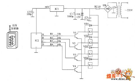

The remote control electric hoist control circuit consists of the wireless transmitter, wireless receiver control circuit and the main control circuit. Wireless transmitter uses TWH9326 four key BP transmitter. Wireless receiver control circuit consists of the power supply circuit, wireless receiver integrated circuit IC2 and control implementation circuit, and it is shown in Figure 1. Control implementation circuit consists of the resistors R1 ~ M, transistors V1 ~ V4, diodes VDi ~ VD4 and relays K1 ~ D4. R1 ~ R4 select the 1/4W metal film resistors; R5 selects the 2V metal film resistor.
(View)
View full Circuit Diagram | Comments | Reading(7112)
Temperature controller circuit diagram 1
Published:2011/8/15 1:25:00 Author:Ecco | Keyword: Temperature controller

The intermittent controller circuit is composed of the power supply circuit, timer and control implementation circuit, and it is shown as the chart. Power supply circuit is composed of the capacitors C2 ~ C4, resistors R3 ~ R5, bridge rectifier UR, power regulator diode VS, and power indication light-emitting diode VL. The timer circuit is composed of counter / divider integrated circuit IC, capacitor C1, diodes VD2 ~ VD4 and resistors R1, R2, R6. R1, R2, C1 and IC internal circuit form the clock oscillator circuit, and the oscillation period (T) value is decided by R2 and C1. Control implementation circuit consists of the transistor V, resistor R7, diode VD1, AC contactor KM and relay K.
(View)
View full Circuit Diagram | Comments | Reading(750)
Three-phase AC constant phase sequence controller circuit diagram
Published:2011/8/15 21:40:00 Author:Ecco | Keyword: Three-phase AC , constant phase sequence , controller

The three-phase AC constant phase sequence controller circuit is composed of the power supply circuit, phase detection circuit and control circuit, and it is shown as the chart. Power supply circuit consists of the power transformer T, bridge rectifier UR, resistor M, regulator diode VS4 and filter capacitor C. Phase sequence detection circuit consists of the rectifier diodes YD1 ~ VD3, current-limiting resistors R1 ~ R3, zener diodes VS1 ~ VS3 and Schmitt trigger NAND gate integrated circuit IC1 internal D1 ~ D3. The control circuit is composed of the JK flip-flop IC IC2, resistor R5, transistor V, diode VD4, relay K and AC contactors KM1, KM2.
(View)
View full Circuit Diagram | Comments | Reading(3433)
| Pages:563/2234 At 20561562563564565566567568569570571572573574575576577578579580Under 20 |
Circuit Categories
power supply circuit
Amplifier Circuit
Basic Circuit
LED and Light Circuit
Sensor Circuit
Signal Processing
Electrical Equipment Circuit
Control Circuit
Remote Control Circuit
A/D-D/A Converter Circuit
Audio Circuit
Measuring and Test Circuit
Communication Circuit
Computer-Related Circuit
555 Circuit
Automotive Circuit
Repairing Circuit