
Circuit Diagram
Index 566
Eggs hatching incubator circuit diagram 4
Published:2011/8/10 2:18:00 Author:Ecco | Keyword: Eggs hatching incubator

The eggs hatch incubator circuit is composed of the power supply circuit, constant temperature control circuit and sound and light alarm circuit, and it is shown in Figure 4-7. Power supply circuit consists of the power switch Sl, fuse FU2, power transformer T and rectifier diodes VD3-VD6. Temperature control circuit consists of the electric contact thermometer Ql, resistors Rl-R3, capacitors Cl, C2, thyristor VTl, diode VD9, relay K, light-emitting diodes VLl and manual / automatic switch S2. Sound and light alarm circuit consists of the electric contact thermometer Q2, resistors R4-Rg, capacitors C3-C6, transistors VT2, VT3, diodes VDl, VD2, VD7, VD8, light-emitting diodes VL2, VL3 and buzzer HA.
(View)
View full Circuit Diagram | Comments | Reading(5370)
Eggs hatching incubator 3
Published:2011/8/10 2:23:00 Author:Ecco | Keyword: Eggs hatching incubator

The eggs hatch incubator circuit is composed of the power supply circuit and temperature control circuit, and it is shown in Figure 4-6. The power supply circuit consists of the step-down capacitor Cl, discharge resistor R8, rectifier diode VD, filter capacitor C2 and zener diode VS. Temperature control circuit consists of the resistors Rl- R7, potentiometer RP, thermistor RT, transistor VT and thyristors Vl-V3. Rl-R8 select the 1/4W metal film resistors or carbon film resistors. RT uses the negative temperature coefficient thermistor. RP uses synthetic membrane potential, or precision multi-turn potentiometer.
(View)
View full Circuit Diagram | Comments | Reading(1430)
Eggs automatic incubator 3
Published:2011/8/10 2:48:00 Author:Ecco | Keyword: Eggs automatic incubator

The eggs automatic incubator circuitis composed ofthe power supplycircuit, temperature / ventilation control circuit,eggs automatically turning circuit and temperature indication circuit, and it isshown in Figure 4-3. Power supply circuit consists of the power switch S3, power transformer T, bridge rectifier UR and capacitors C2-C4, current limiting resistor Rl2, zener diode VS. Eggs automatically turning circuit consists of resistors Rl3-R16, potentiometer RP6, capacitors C7-C9, time-base integrated circuit IC2, transistor V3, diode VD2, relay K2, limit switch Sl, trigger switch and DC electric motor M2 . IC2 and its external RC components form the steady-state circuit; V3 and Rl3, R14, VD2, K2 and Sl form the the control circuit of M2.
(View)
View full Circuit Diagram | Comments | Reading(2521)
UC3842AN PWM IC diagram
Published:2011/8/11 1:15:00 Author:Ecco | Keyword: PWM IC
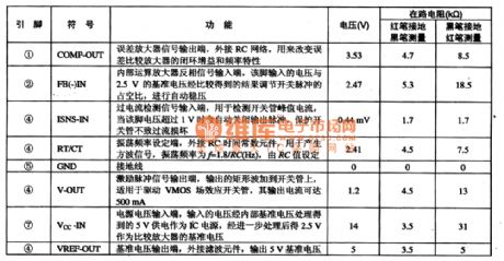

UC3842AN PWM pulse width modulation integrated circuit, which is widely used in DVD, VCD, SVCD DVD players, computers and display systems, and various other household appliances switching power supply circuits. 1. FeaturesUC3842AN integrated circuit contains the pulse signal generator, voltage regulator, pulse width adjustment circuit, voltage and current detection circuit. The internal manifold block diagram and typical application circuit are shown in Figure 1-1.
(View)
View full Circuit Diagram | Comments | Reading(7115)
Humidity detection circuit diagram composed of H104R humidity sensor
Published:2011/8/15 1:09:00 Author:Ecco | Keyword: Humidity detection , humidity sensor

Figure 1 is the humidity detection circuit composed of H104R humidity sensor. In the circuit, the AC voltage is added to the humidity sensor, and the circuit consists of the oscillation circuit, buffer, rectifier circuit, temperature compensated differential amplifier circuit, humidity output amplifier circuit, temperature detection circuit,temperature output amplifier circuit. The circuit's power supply voltage is ± l2V, the oscillation frequency of the oscillation circuit is 1KHz. Compensation characteristics of the sensor is decided by R1, R2, R3. The temperature coefficient of RH humidity resistor H104R is 0.7% RH / ℃. Thermistor RT is commonly used in temperature compensation circuit.
(View)
View full Circuit Diagram | Comments | Reading(2602)
LR4087 microcomputer dial IC diagram
Published:2011/8/11 20:06:00 Author:Ecco | Keyword: microcomputer dial IC

LR4087 is a micro-computer dial integrated circuit, which is used in communication equipment as dial-up circuit. LR4087 integrated circuit contains two-tone dialing generator, keyboard switch codec circuit, squelch control circuit. LR4087 IC uses 16-pin dual in-line package, and the integrated circuit pin functions and data are listed in Table 1.
(View)
View full Circuit Diagram | Comments | Reading(1151)
Eggs automatic incubator 2
Published:2011/8/8 22:18:00 Author:Ecco | Keyword: Eggs automatic incubator
The eggs automatic incubator circuit is composed of the power supply circuit, temperature control circuit, temperature detection control circuit and egg timing turning circuit, and it is shown in Figure 4-2. Power supply circuit consists of the power switch S, power light HLl, power transformer T, bridge rectifier UR, filter capacitors C7-ClO and three-terminal voltage regulator integrated circuit IC2. Temperature detection control circuit consists of the resistors Rl-R6, capacitors Cl-C4, transistors Vl, V2, thermistor RT, thyristor VTl, heating lamp HL2 and heater EH. Vl uses 59013 or C8050, 3DG9013 silicon NPN transistor.
(View)
View full Circuit Diagram | Comments | Reading(2809)
Eggs automatic incubator 1
Published:2011/8/8 22:15:00 Author:Ecco | Keyword: Eggs automatic incubator
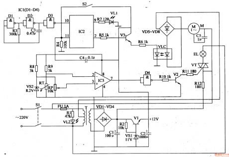
The eggs automatic incubator circuit is composed of the power supply circuit, automatic egg turning control circuit and temperature control circuit and other components, and it is shown in Figure 4-1. Power supply circuit is composed of the power switch Sl, fuse FU, power transformer T, rectifier diodes VDl-VD4, filter capacitors Cl, C2, resistors Rl, R2, power indicator LED VL2, voltage regulator VSl and power regulator diode VI. Rl-Rll select the 1/4W carbon film resistors or metal film resistors; Rl2 select the lW metal film resistor.
(View)
View full Circuit Diagram | Comments | Reading(2841)
High temperature disinfection cabinet
Published:2011/8/10 2:34:00 Author:Ecco | Keyword: High temperature , disinfection cabinet
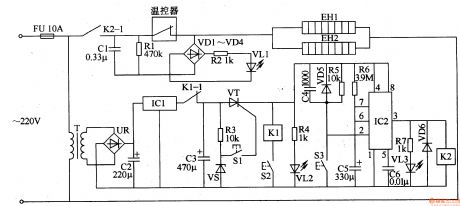
The high temperature disinfection cabinet circuit is composed of the power supply circuit, control circuit and indication circuit, and it is shown in Figure 3-210. Power supply circuit consists of the thermal fuse FU, power transformer T, bridge rectifier UR, three-terminal regulator IC lCl and filter capacitors C2, C3. Indication circuit is composed of the LEDs VLl-VL3, rectifier diodes VDl-VD4, resistors Rl, R2, R4, R7, step-down capacitor Cl and other components. The control circuit consists of the thyristor VT, relays Kl, K2, time-base integrated circuit lC2, control buttons Sl-S3, thermostat, resistors R3, R5, R6, diodes VD5, VD6 and zener diode VS.
(View)
View full Circuit Diagram | Comments | Reading(1274)
Microwave turn-off delay device
Published:2011/8/14 22:52:00 Author:Ecco | Keyword: Microwave , turn-off delay device

The microwave delay-off circuit is composed of the power supply circuit and delay control circuit, and it is shown in Figure 3-209. Power supply circuit consists of the nonstick button switch Sa, step-down capacitor Cl, resistor Rl, rectifier diodes VDl-VD4, voltage regulator diode VS and filter capacitor C2. Delay control circuit consists of op-amp integrated circuit IC, transistor V, relay K, delay capacitor C4, button switch Sb, current transformer TA, diodes VD5-VD7, resistor R7 and other components. Rl selects the 1/2W carbon film resistors; R2-R7 use the l/8W or 1/4W carbon film resistors.
(View)
View full Circuit Diagram | Comments | Reading(1516)
Water power off and open controller
Published:2011/8/8 21:42:00 Author:Ecco | Keyword: Water controller, power off , power open

This water power off and open controller circuit described in the example is composed of the power supply circuit and control circuit, and it is shown in Figure 3-208. The power supply circuit consists of the step-down capacitor Cl, rectifier diodes VDl and VD2, current limiting resistor Rl, filter capacitor C2, Zener diode VS and other components. Control circuit consists of resistor R5, humidity sensitive resistor RS, thyristor Vn, Triac VTl. EH is the heater on the kettle. Rl chooses 2W metal film resistor; R2, R3, R5 select the 1/4W metal film resistors; R4 select the membrane variable resistor.
(View)
View full Circuit Diagram | Comments | Reading(700)
LBl690 high performance brushless DC motor control circuit diagram
Published:2011/8/15 20:42:00 Author:Ecco | Keyword: high performance , brushless , DC motor control


LBl690 is the three-phase brushless DC motor drive control integrated circuit produced by Japanese Sanyo, and it is widely used in domestic and imported broken wind , fresh air-condition brushless DC drive control. 1. FeaturesLBl690 IC has the over-current limiting, thermal shutdown circuit, HALL tape amplifier, FG output circuit. Pressure is 45V with 2.5 A current output. The manifold internal block diagram and typical application circuit are shown in Figure 1.
(View)
View full Circuit Diagram | Comments | Reading(5053)
AV equipment order open, shut down controller
Published:2011/8/11 20:17:00 Author:Ecco | Keyword: AV equipment, order open controller, shut down controller
The AV equipment order open, shut down controller circuit is composed of the power supply circuit and control circuit, and it is shown in Figure 3-207. Power supply circuit consists of the power transformer T, bridge rectifier UR, filter capacitors C6, C7, three-terminal voltage regulator integrated circuit, resistor R14 and power indicator LED VLl. Control circuit consists of the control switch S, resistors Rl-R13, capacitors Cl-C5, operational amplifier integrated circuit (Nl-N4), diodes VDl-VD4, transistors Vl-V4, relays Kl-K4 and outlets XSl-XS4. Rl-R14 select the 1/4W metal film resistors.
(View)
View full Circuit Diagram | Comments | Reading(609)
Electric fan anti-injured controller
Published:2011/8/14 22:44:00 Author:Ecco | Keyword: Electric fan , anti-injured controller

The electric fan anti-injured controller circuit is composed of the power supply circuit, touching power-off circuit, brake circuit and alarm circuit, and it is shown in Figure 3-206. Power supply circuit is composed of the power transformer T, rectifier diodes VDl-VD4, filter capacitor Cl and voltage-regulator diode VS. Touching power- off circuit is composed of touching pad A, time-base integrated circuit lCl, relay Kl and the RC components. Braking circuit is composed of the relay driver transistor V2, capacitors C3, C4 and resistor R5 and so on. Alarm circuit is composed of the music integrated circuit IC2, transistor Vl, speaker BL and resistors R4, R6 and so on.
(View)
View full Circuit Diagram | Comments | Reading(2199)
Washing machine electronic program controller
Published:2011/8/15 21:11:00 Author:Ecco | Keyword: Washing machine, electronic program controller

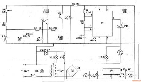
The washing machine electronic program controller circuit is composed of the power supply circuit, multivibrator, flip-flop and control implementation circuit, and it is shown in Figure 3-205. Power supply circuit is composed of the power switch S, buck capacitor C2, resistor R8, rectifier diodes VD4, VD5, voltage regulator diode VS and filter capacitor C3. Multivibrator integrated circuit is composed of the time-base ICl, resistors Rl-R3, capacitor Cl and the normally closed contacts Kl-l, K2-1 of relays Kl, K2. Trigger consists of the voice control circuit IC2, diode VDl, resistors R4, R5 and capacitor C4.
(View)
View full Circuit Diagram | Comments | Reading(5021)
AV source selector
Published:2011/8/11 22:43:00 Author:Ecco | Keyword: AV source selector
AV source selector circuit is composed of the power supply circuit, AV signal selection circuit and power control circuit, and it is shown in Figure 3-204. Power supply circuit is composed of the power transformer T, bridge rectifier UR, filter capacitors Cl5-C18 and three-terminal voltage regulator integrated circuit IC2. AV signal selection circuit is composed of the high-frequency analog switch integrated circuits ICl, resistors Rl-Rl5, capacitors Cl-C14 and the signal outlets XSl-XSl2. Power control circuit is composed of the selector switch S, transistors Vl-V3, relays Kl-K3, diodes VDl-VD3, LEDs VLl-VL3, resistors Rlg-R22 and the outlets XSl3-XSl7.
(View)
View full Circuit Diagram | Comments | Reading(917)
Sound source selector
Published:2011/8/14 22:35:00 Author:Ecco | Keyword: Sound source selector

The sound source selector circuit is composed of the transistor V, diode VD, thyristors VTl-VW, control buttons Sl-S4, sound source indication LEDs VLl-VL4, relays Kl-K4, resistor Rl, audio input jacks XSI- XS8, and it is shown in Figure 3-203. Rl and R2 select the 1/4W or 1/8W carbon film resistors. Cl-C4 select the aluminum electrolytic capacitors with voltage in 16V. VD selects the lN4001 or 1N4007 silicon rectifier diode. VLl-VL4 use theφ3 or φ5mm light emitting diodes with different colors. V uses the S9014, C8050 or 3DGl2 silicon NPN transistors.
(View)
View full Circuit Diagram | Comments | Reading(5616)
Fluorescent lamp electronic ballast
Published:2011/8/14 22:45:00 Author:Ecco | Keyword: Fluorescent lamp, electronic ballast
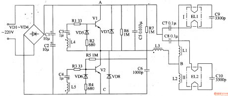
The fluorescent lamp electronic ballast circuit is composed of the rectifier filter circuit, high-frequency oscillator circuit and output circuit, and it is shown in Figure 3-202. Rectifier filter circuitis composed of the rectifier diodes VDl-VD4 and filter capacitors Cl, C2. High-frequency oscillator consists of the transistors VI, V2, resistors Rl-R7, capacitors C3, C4, C6, diodes VD5-VD8 and inductors L3-L5 (L3-L5 is wound in the same magnetic ring to form a high-frequency transformer). Output circuit consists of the chokes Ll, L2 (stabilizing current) and capacitors C7-ClO. Rl-R7 use 1/4W carbon film resistors or metal film resistors.
(View)
View full Circuit Diagram | Comments | Reading(9888)
Auto-dimming lamp
Published:2011/8/15 21:07:00 Author:Ecco | Keyword: Auto-dimming lamp

The auto-dimming lamp circuit is composed of the power supply circuit and light control circuit, and it is shown in Figure 3-201. Power supply circuit is composed of the power switch S, filter capacitors Cl, C2, inductor L, bridge rectifier UR, current limiting resistor Rl and the voltage regulator diode VS. Light control circuit is composed of the photosensitive resistor RG, resistor R4, potentiometer RP, capacitor C3, transistor V1, two-way trigger diode V2 and thyristor VT. Rl selects the 1/2W metal film resistor; R2-R4 use the 1/4W carbon film resistors or metal film resistors. RP uses the solid organic or synthetic membrane potentiometer.
(View)
View full Circuit Diagram | Comments | Reading(1763)
Incandescent life extension device 1
Published:2011/8/10 3:52:00 Author:Ecco | Keyword: Incandescent, life extension device

The incandescent life extension device circuit is composed of the rectifier diodes VDl-VD4, thyristor VT, resistors Rl-R4, capacitor C, voltage regulator diode VS and transistor V, and it is shown in Figure 3-197. Rl-R4 use 1/4W carbon film resistors or metal film resistors. C uses the high-frequency ceramic capacitor. VDl-VD4 select the 1N4007 silicon rectifier diodes. VS selects the 1/2W, 24V silicon zener diode. V uses C8050 or S8050, 3DGl2 other types of silicon NPN transistor. VT uses MCRlO0-6 or MCRlO0-8, BTl69D thyristor.
(View)
View full Circuit Diagram | Comments | Reading(687)
| Pages:566/2234 At 20561562563564565566567568569570571572573574575576577578579580Under 20 |
Circuit Categories
power supply circuit
Amplifier Circuit
Basic Circuit
LED and Light Circuit
Sensor Circuit
Signal Processing
Electrical Equipment Circuit
Control Circuit
Remote Control Circuit
A/D-D/A Converter Circuit
Audio Circuit
Measuring and Test Circuit
Communication Circuit
Computer-Related Circuit
555 Circuit
Automotive Circuit
Repairing Circuit