Amplifier Circuit
The light chasing beetle circuit
Published:2011/8/15 21:16:00 Author: | Keyword: light chasing, beetle | From:SeekIC

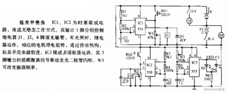
The light chasing beetle circuit Both IC1 and IC2 are the time-based integrated circuits, and they are fixed in the non-steady working state. The 3 pin output by it control relay J1, J2 and J3 respectively, the 4-pin is linked with the LST. When there is light, the relay is working, and the relative motor is running, with the help of the driving gear, the toy beetle is going forward. IC3 is a multi-resonance oscillator circuit, whose 3-pin outputs the low oscillating signal which drives the LED to flash, W3 can change the oscillating frequency.
Reprinted Url Of This Article:
http://www.seekic.com/circuit_diagram/Amplifier_Circuit/The_light_chasing_beetle_circuit.html
Print this Page | Comments | Reading(3)

Article Categories
power supply circuit
Amplifier Circuit
Basic Circuit
LED and Light Circuit
Sensor Circuit
Signal Processing
Electrical Equipment Circuit
Control Circuit
Remote Control Circuit
A/D-D/A Converter Circuit
Audio Circuit
Measuring and Test Circuit
Communication Circuit
Computer-Related Circuit
555 Circuit
Automotive Circuit
Repairing Circuit
Code: