Electrical Equipment Circuit
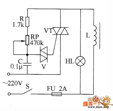
Industrial degaussing device circuit diagram
Published:2011/8/10 21:21:00 Author:Ecco | Keyword: Industrial degaussing device | From:SeekIC

The industrial degaussing device circuit is composed of the fuse FU, thyristor VT, two-way trigger diode V, degaussing coil L, resistor R, potentiometer RP, capacitor C, LED HL, fuse FU and power switch s, and it is shown as the chart. R selects the 1/2W metal film resistor. RP chooses the potentiometer or solid synthetic organic carbon potentiometer with voltage being more than 2W. C uses the CBB capacitor polyester capacitor with the voltage in 250V. V uses the DB3 or 2CTS two-way trigger diode. VT uses the 100V, 10A two-way intergranular tube. HL chooses the 15W, 220V incandescent bulb. S selects the 5A, 220V power switch.
Reprinted Url Of This Article:
http://www.seekic.com/circuit_diagram/Electrical_Equipment_Circuit/Industrial_degaussing_device_circuit_diagram.html
Print this Page | Comments | Reading(3)

Article Categories
power supply circuit
Amplifier Circuit
Basic Circuit
LED and Light Circuit
Sensor Circuit
Signal Processing
Electrical Equipment Circuit
Control Circuit
Remote Control Circuit
A/D-D/A Converter Circuit
Audio Circuit
Measuring and Test Circuit
Communication Circuit
Computer-Related Circuit
555 Circuit
Automotive Circuit
Repairing Circuit
Code: