Remote Control Circuit
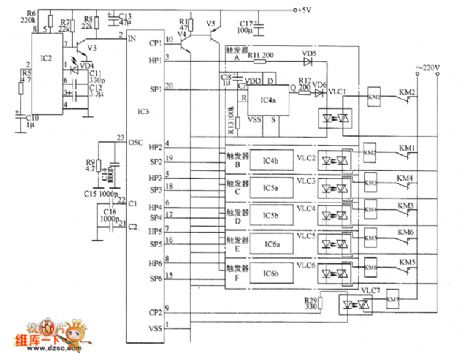
Remote control electric hoist control circuit diagram 2
Published:2011/8/15 22:07:00 Author:Ecco | Keyword: Remote control, electric hoist control | From:SeekIC


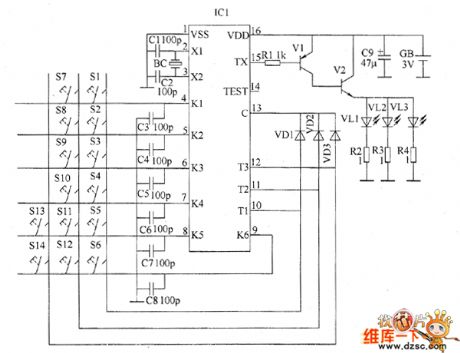
The remote control electric hoist control circuit consists of the infrared transmitter and infrared receiver control circuit. Infrared transmitter circuit is composed of the infrared emission coding circuit and peripheral components of integrated circuit ICI, and it is shown in Figure 1. Control buttons S1 ~ S4, diodes VD1 ~ VD3, capacitors C3 ~ C8 and IC1's pin 4 to 13 internal circuit form the keying input circuit; capacitors C1 and C2, quartz crystal oscillator BC and IC1'S pin 2,3 internal circuit form the oscillator circuit; resistors RI ~ M, transistors VI and infrared light-emitting diodes VL1 ~ VL3 and IC1's pin 15 internal circuit form the infrared driver circuit.
Reprinted Url Of This Article:
http://www.seekic.com/circuit_diagram/Remote_Control_Circuit/Remote_control_electric_hoist_control_circuit_diagram_2.html
Print this Page | Comments | Reading(3)

Article Categories
power supply circuit
Amplifier Circuit
Basic Circuit
LED and Light Circuit
Sensor Circuit
Signal Processing
Electrical Equipment Circuit
Control Circuit
Remote Control Circuit
A/D-D/A Converter Circuit
Audio Circuit
Measuring and Test Circuit
Communication Circuit
Computer-Related Circuit
555 Circuit
Automotive Circuit
Repairing Circuit
Code: