Position: Home > Circuit Diagram > Electrical Equipment Circuit > Other Circuit > Synchronous Rectifier Buck Chopper Circuit
Other Circuit
Synchronous Rectifier Buck Chopper Circuit
Published:2011/8/13 6:10:00 Author:Robert | Keyword: Synchronous, Rectifier, Buck, Chopper | From:SeekIC

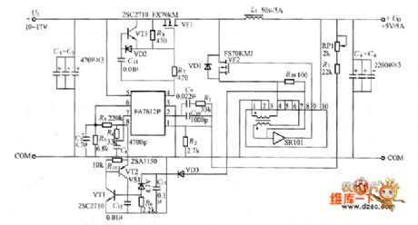
The circuit, which uses the synchronous rectifier buck chopper and has the output of 5V/5A, is shown in the picture. In the circuit, VF2 is the MOSFET used for synchronous rectifier. The SR101 is synchronous driving module. If connecting the diode VD1's positive electrode to the ground it would make up the traditional buck chopper circuit.
The picture shows the synchronous rectifier buck chopper circuit.
Reprinted Url Of This Article:
http://www.seekic.com/circuit_diagram/Electrical_Equipment_Circuit/Other_circuit/Synchronous_Rectifier_Buck_Chopper_Circuit.html
Print this Page | Comments | Reading(3)

Article Categories
power supply circuit
Amplifier Circuit
Basic Circuit
LED and Light Circuit
Sensor Circuit
Signal Processing
Electrical Equipment Circuit
Control Circuit
Remote Control Circuit
A/D-D/A Converter Circuit
Audio Circuit
Measuring and Test Circuit
Communication Circuit
Computer-Related Circuit
555 Circuit
Automotive Circuit
Repairing Circuit
Code: