Signal Processing
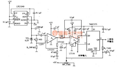
Random code generation circuit composed of the LTC1340
Published:2011/8/23 22:29:00 Author: | Keyword: Random code, generation circuit | From:SeekIC

The random code generation circuit which is composed of the LTC1340 is as shown in the figure. This circuit uses the 6.2V voltage-regulator diode VD1 to produce the random noise with the best features. We can find that this circuit outputs the best noise at the bending place of the zener diode characteristic curve, it is the starting place of the 6.2V stable voltage. The operating voltage of the circuit is +5V. In order to let the VD1 get the 6.2V stable voltage, we use the LTC1340 as the boost converter to improve the +5V to +8V (the output voltage of the pin-7 is 9.2V). The resistors R1 and R2 supply the 1.25V bias voltage to A1 to make it match with the input common-mode signal range of the comparator A2.
Reprinted Url Of This Article:
http://www.seekic.com/circuit_diagram/Signal_Processing/Random_code_generation_circuit_composed_of_the_LTC1340.html
Print this Page | Comments | Reading(3)

Article Categories
power supply circuit
Amplifier Circuit
Basic Circuit
LED and Light Circuit
Sensor Circuit
Signal Processing
Electrical Equipment Circuit
Control Circuit
Remote Control Circuit
A/D-D/A Converter Circuit
Audio Circuit
Measuring and Test Circuit
Communication Circuit
Computer-Related Circuit
555 Circuit
Automotive Circuit
Repairing Circuit
Code: