
Circuit Diagram
Index 556
The gain adjustable addition circuit composed of CF725
Published:2011/8/16 22:26:00 Author:Rebekka | Keyword: gain adjustable addition


The circuit uses integrated operational amplifier CF725. The op amp is a monolithic precision operational amplifier with low power consumption, high voltage gain. It can be used for instrumentation etc.
The component values of frequency compensation network.
The typical main parameters of CF725.
(View)
View full Circuit Diagram | Comments | Reading(618)
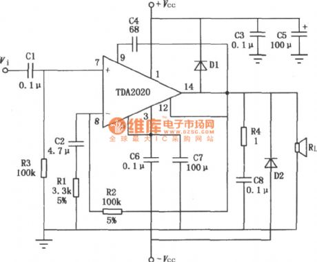
Typical application circuit diagram of 20W Hi—Fi audio power amplifier TDA2020
Published:2011/8/17 1:27:00 Author:Rebekka | Keyword: 20W Hi—Fi, Audio power amplifier , typical application
View full Circuit Diagram | Comments | Reading(2825)
Op-amp relay delay release circuit diagram
Published:2011/8/17 2:30:00 Author:Rebekka | Keyword: Op-amp relay , delay release

The figure shows the relay delay release circuit composed of operational amplifier circuit. When the power switch is turned on, the operational amplifier inverse input is added the voltage VTbetween the 4.7kΩ and 10 k Ω resistor, C1 has not charged, the same phase input is the low level. So operational amplifier output terminal is low level, the relays pulls in. At the same time, the power supply passes the 1.2 M Ω resistance and charge for the capacitor C1. Along with the increase of the capacitance C1, its charge voltage increases gradually. A period of time later the voltage will bein high level. (View)
View full Circuit Diagram | Comments | Reading(1476)
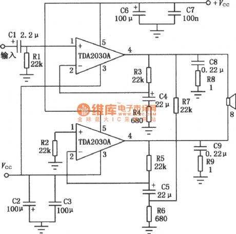
BTL application circuit diagram of TDA2030A audio power amplifier
Published:2011/8/17 2:25:00 Author:Rebekka | Keyword: Audio power amplifier , BTL application
View full Circuit Diagram | Comments | Reading(6616)
ULN3702Z/TDA2002A 12W audio power amplifier circuit diagram
Published:2011/8/17 2:24:00 Author:Rebekka | Keyword: 12W , audio power amplifier

ULN3702Z/TDA2002A are audio power amplifier integrated circuits,and theyuse the 5 feet into plastic packaging. The single inline radiator stents grounding potential, so no need to add insulation measures between the integrated circuits and the heat. According to the shape of the lead tube feet, it is divided into V type and the H two forms. The integrated circuit is ULX37012 / TDA2002 improvement products, the interior has high pressure protection circuit. The work power supply can be up to 26 V power supply voltage, if DC load rated current is 2.5 A, it uses appropriate heat sink, its power can be controlled to 60 W. (View)
View full Circuit Diagram | Comments | Reading(969)
General multi-functional alarm and timer(555) circuit diagram
Published:2011/8/17 3:08:00 Author:Rebekka | Keyword: General multi-functional alarm , timer, 555

General multi-functional alarm and timer(555) circuit diagram is shown as above. The timing range of this circuit can be adjusted from 5 minutrs to 3 hours. 555 Capacitor multiplier circuit is made up of timing components C2, VD1 and VT1.For keeping K1 at timing block and press AN, 555③ pin will output high level(6~9V) and VT2 will be disconnected. When it's time to timing time, 555's pin 3 will turn to low level. CK1 will have no voltage output and VT2 will be conducted. The alarm circuit composedof F1 and F2 will produce 20 seconds alarm ,and F3 to F5 will produce light alarm. A and B ends can be added a variety of sensors to make up of an additional acoustic and optical alarm circuit. (View)
View full Circuit Diagram | Comments | Reading(1140)
5V fixed voltage power supply circuit diagram with over cut-off protection
Published:2011/8/17 3:05:00 Author:Rebekka | Keyword: Over cut-off protection, fixed voltage power supply, 5V

View full Circuit Diagram | Comments | Reading(1124)
M50195 Digital echo delayed application interface circuit diagram
Published:2011/8/17 3:04:00 Author:Rebekka | Keyword: Digital echo, delayed application

View full Circuit Diagram | Comments | Reading(3477)
Q measurement incentive driver circuit diagram
Published:2011/8/17 3:03:00 Author:Rebekka | Keyword: Q measurement incentive driver

View full Circuit Diagram | Comments | Reading(509)
Flat Vacuum Microelectronic flat camera tube 10×10 pixel-driven circuit diagram
Published:2011/8/17 3:02:00 Author:Rebekka | Keyword: Flat Vacuum Microelectronic, 10×10 pixel-driven, flat camera tube
View full Circuit Diagram | Comments | Reading(547)
Threshold voltage compensation analog driver circuit diagram
Published:2011/8/17 3:01:00 Author:Rebekka | Keyword: voltage compensation , threshold analog driver

View full Circuit Diagram | Comments | Reading(807)
Voltage control drive circuit diagram with subthreshold current compensation and threshold voltage changing
Published:2011/8/17 3:00:00 Author:Rebekka | Keyword: Voltage control drive , subthreshold current compensation , threshold voltage changing

View full Circuit Diagram | Comments | Reading(711)
High power led driver boost regulator circuit diagram
Published:2011/8/17 2:57:00 Author:Rebekka | Keyword: High power , led driver , boost regulator

When the input voltage of LED system applications is less than the minimum entire series string of forward voltage drop, you need a boost regulator. In the low-power applications, the switched capacitor boost converter is widely used. However, when the current is about 100mA or more, the efficiency will drop rapidly. Inductive boost regulators also need some output voltage to provide a higher part of the input voltage.
Picture: High power led drive boost regulator circuit.It chooses an circuit that is used for driving an LED array typical step-up regulator. The reduction voltage circuit is shown in figure 3a and 3b. Previously it is allowed the dynamic movement in the output current while the output voltage regulation system. It has been converted to allow the dynamic movement in the output voltage andoutput current while maintaining the system at present.
(View)
View full Circuit Diagram | Comments | Reading(3066)
Regulated power supply circuit diagram composed of L296 monolithic high-current switching power supply chip
Published:2011/8/17 2:54:00 Author:Rebekka | Keyword: Regulated power supply , monolithic high-current , switching power supply chip

The features of L296 monolithic high-current switching power supply chip are: (1) Perfect protection function. It is equipped with soft start, over current, overheating, overvoltage protection; (2) The maximum output current is 4A, 160W power, output voltage is adjustable between 5.1 ~ 40V; (3) Special features: Workban control, synchronization control(in a few pieces long on output, to ensure the same frequency), reset circuit (power supply can provide state of the detection signal), crowbar overvoltage protection circuit(When the output voltage exceeds a preset 20% rated. It produces a 100mA of drive signals for triggering external protection circuit action). Figure (c) shows the current expansion of the circuit form. (View)
View full Circuit Diagram | Comments | Reading(4358)
Optical wand amplifier circuit diagram
Published:2011/8/17 2:46:00 Author:Rebekka | Keyword: Optical wand amplifier
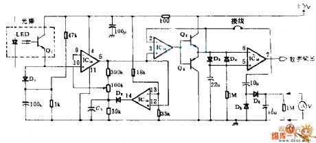
This circuit is mainly composed of light rods and four operational amplifier IC1, amplifier, and Lee silicon diode's exponential positive electrical properties can change the output of light rods into logarithmic e transformation voltage changes, its peak - peak is proportional to the white, black light currents ratio, and it has nothing to do with the absolute value. IC1b, which is the comparator, and peak detection D2-C1 clamp the output of amplifier IC1 to a fixed potential. Thus, the signal after amplification and clamping is transformed into binary digital microprocessor output. Output is compatible with TTL.
(View)
View full Circuit Diagram | Comments | Reading(673)
TD4919 switch regulator power supply circuit diagram composed of switching power supply IC
Published:2011/8/17 2:38:00 Author:Rebekka | Keyword: switch regulator, power supply , switching power supply

The AC input voltage of the circuit is 185~240V, DC output voltage is 10V, output current is 5A. The features are: It has the function of monitoring output voltage, overvoltage and undervoltage and the function of dynamic current limit.
Regulation process is: Output voltage Vo passes R15 and PR partial pressure trough R16 and R17 feedback to pin18 and pin 19 of TD4919. The internal control of TD4919 is used to adjust its output switch pulse duty cycle to reach a stable output voltage Vo. The monitor of power supply output current is realised by the sample voltage of R11 monitoring(R11 is the sample voltage of VT source current). It produces control signalto control the output switch pulse to achieve the limit of output current. Undervoltage and overvoltage monitoring is achieved by R4, R5, R6, pin12, pin13 and the internal control circuit of TD4919. (View)
View full Circuit Diagram | Comments | Reading(1392)
555 water level control circuit diagram composed of 555 and music circuit
Published:2011/8/17 2:35:00 Author:Rebekka | Keyword: 555 , water level control , music circuit
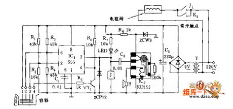
1, 2, 3, 4 are four probes. When the surface declines and pin 3 exposes, the pin2 of IC1 is a low level(<1/3 VDD). 555 sets, J pull-in, solenoid valve starts to work and water injects to container. At the same time, IC2 is triggered and play a song to inform you it is going to inject water. When the water resistance between 1 and 2 makes the potential of pin6 rises higher than 2/3VDD and trigger the level, 555 resets, pin 3 turns to low level. J releases, the solenoid valve power turns off. Probe 4 is insurance probe, when the surface of water rises to probe 4 because of any reasons, VT1 will be conducted and turned to a low level, it forces 555 resetting and turning off the solenoid valve. (View)
View full Circuit Diagram | Comments | Reading(2657)
Switch regulator power supply circuit diagram made by three-terminal regulator
Published:2011/8/17 3:20:00 Author:Rebekka | Keyword: three-terminal regulator , switch regulator power supply


Equivalent circuit of switching regulator power supply:
Switch regulator power supply circuit diagram made by three-terminal regulator is shown as above. Itsworking principle can be read through the equivalent circuit diagram. The output voltage VO declines a little because of some reasons. The partial pressure V3 on R5 and R6 also declines. It is enlarged by VT3, then Ic3 minishes, Ic2 increases, the current passing R1 and VD1 increases, V1 declines. It makes Ic1 increase, V4 rise, V4 passing the partial voltage of R2 and R3, V2 increase and V3 decline. The process is a reaction of positive chain feedback. Finally VT1 and VT2 are conducted, VT3 stops, Ic1 charges to L1 and C1. It makes Vo increase gradually. (View)
View full Circuit Diagram | Comments | Reading(733)
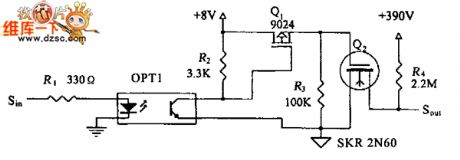
Impulse amplifier circuit diagram
Published:2011/8/17 3:17:00 Author:Rebekka | Keyword: Impulse amplifier

The circuit Motorola MOC 1000 optical isolator can make digital logic coupling use different supply voltages or different ground systems. At the same time, it provides almost complete isolation. The circuit can satisfy the instrumentation requirements in the transfer characteristic and have sufficient drive capability. It can be used for driving low input impedance loads. (View)
View full Circuit Diagram | Comments | Reading(957)
The water level control circuit diagram composed of reduction voltage rectification circuit and 555
Published:2011/8/17 3:16:00 Author:Rebekka | Keyword: water level control , reduction voltage rectification , 555
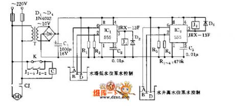
To achieve the automatic control of water tower and water level,probes B and D are put in well. Under normal circumstances, it should be in a certain depth of water level. It makes the output terminal 3 of IC2(555) circuit turn to low level, J2 pull-in, J2-2 closed. Pumping continuously makes polar B and polar D expose from water, pin 2 turn to a low level. It makes IC2 turn-over position, pin3 turn to a high level, J2 release, J2-2 disconnect to avoid motor from idle running, then it willmonitor the water level of the well. (View)
View full Circuit Diagram | Comments | Reading(3143)
| Pages:556/2234 At 20541542543544545546547548549550551552553554555556557558559560Under 20 |
Circuit Categories
power supply circuit
Amplifier Circuit
Basic Circuit
LED and Light Circuit
Sensor Circuit
Signal Processing
Electrical Equipment Circuit
Control Circuit
Remote Control Circuit
A/D-D/A Converter Circuit
Audio Circuit
Measuring and Test Circuit
Communication Circuit
Computer-Related Circuit
555 Circuit
Automotive Circuit
Repairing Circuit