
Circuit Diagram
Index 551
Practical pulse signal generator circuit diagram
Published:2011/8/10 3:53:00 Author:nelly | Keyword: pulse, signal generator

As shown in the figure, it is a practical pulse signal generator with adjustable duty cycle. The pulse frequency generator circuit is composed of A1 and some peripheral devices, it connects three different capacitors which have three different frequency measuring range, RP1 is used to accurately adjust the frequency. The modulation signal generator circuit consists of A3 and some peripheral devices, it also has three kinds of measuring range, RP2 is used to accurately adjust the frequency signal. RP3 is used to the gain adjust of modulation signal. RP4 controls the duty cycle.
(View)
View full Circuit Diagram | Comments | Reading(852)
The reverse phase dual triangle wave generator
Published:2011/8/17 20:35:00 Author: | Keyword: Reverse phase, dual triangle wave, generator

View full Circuit Diagram | Comments | Reading(753)
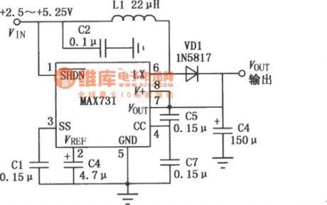
MAX731 switch control DC-DC boosting convertor
Published:2011/8/11 11:25:00 Author:leo | Keyword: Switch, DC-DC boosting convertor
View full Circuit Diagram | Comments | Reading(600)
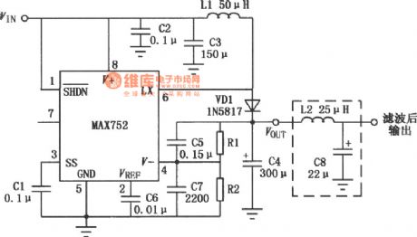
The classic applying circuit of MAX752 setting up switch DC-DC convertor
Published:2011/8/14 7:19:00 Author:leo | Keyword: Classic applying circuit, setting up switch, DC-DC convertor
View full Circuit Diagram | Comments | Reading(577)
The classic applying circuit of MAX743 setting up switch DC-DC convertor
Published:2011/8/14 7:24:00 Author:leo | Keyword: Classic applying circuit, setting up switch, DC-DC convertor

View full Circuit Diagram | Comments | Reading(876)
MM1126~MM1129 setting up DC-DC convertor
Published:2011/8/14 7:22:00 Author:leo | Keyword: DC-DC convertor, setting up

View full Circuit Diagram | Comments | Reading(590)
The scanning generator formed by CD4046
Published:2011/8/14 7:25:00 Author:leo | Keyword: Scanning, generator

View full Circuit Diagram | Comments | Reading(1041)
The oblique wave generator formed by CD4046
Published:2011/8/17 20:33:00 Author: | Keyword: Oblique wave, generator

The oblique wave generator circuit is shown in the picture. It uses two capacitors to finish charging and discharging, which is C2 (connected to pin 6) and C1 (connected to pin 7). The ratio of capability of these two capacitors is 1000:1. When the charging time is shorter than discharging time, it generates a wave whose rising time is 1000 times of lowering time, which is actually the signal of saw wave. (View)
View full Circuit Diagram | Comments | Reading(1629)
The imporved hartley circuit
Published:2011/8/17 20:23:00 Author: | Keyword: Hartley circuit

View full Circuit Diagram | Comments | Reading(601)
Classic Cyle circuit
Published:2011/8/14 7:39:00 Author:leo | Keyword: Classic Cyle circuit

View full Circuit Diagram | Comments | Reading(661)
Voltage regulator DC-DC circuit and power supply monitor pins introduction and main features TA8505 power supply monitoring circuit
Published:2011/8/17 20:20:00 Author: | Keyword: Voltage regulator, power supply monitor, pins introduction and main features, power supply monitoring circuit

TA8505 power supply monitoring circuit When power supply is connected, cut off or voltage changes suddenly, the monitoring circuit will protect the circuit. Its operating voltage is from 1.8 V to 36 V with the output current of 30mA. It permits you set the test voltage or back-off voltage, which can use outer restart signal to carry out restart function. It has a power consumption of 600mW and the work temperature is from -40oC to +85oC. (View)
View full Circuit Diagram | Comments | Reading(849)
The frequency divider circuit with a rate of 34 and made by CD4017
Published:2011/8/14 7:14:00 Author:leo | Keyword: Frequency divider, rate

The frequency divider is formed by two CD4017 and dual input port. It can expand the frequency rate to 2 to 99 through different combinationsand connection, which is shown as following: (View)
View full Circuit Diagram | Comments | Reading(2482)
Constant current power supply circuit made by CW137/CW237/CW337
Published:2011/8/11 11:08:00 Author:leo | Keyword: Constant current, power supply

View full Circuit Diagram | Comments | Reading(976)
The frequency lock indicator formed by CD4046
Published:2011/8/14 7:17:00 Author:leo | Keyword: Frequency lock, indicator

It can design a frequency lock indicator based the output features of two phase compatators of the lock circuit under the condition of locking frequency. (View)
View full Circuit Diagram | Comments | Reading(2527)
Switch constant current power supply applying circuit made by W723
Published:2011/8/11 11:12:00 Author:leo | Keyword: Switch, constant current, power supply

View full Circuit Diagram | Comments | Reading(733)
Low drift contant current power supply circuit made by MIC2951
Published:2011/8/11 11:10:00 Author:leo | Keyword: Low drift, contant current, power supply

View full Circuit Diagram | Comments | Reading(657)
The multi-wave shape generator formed by CD4046
Published:2011/8/14 7:31:00 Author:leo | Keyword: Multi-wave shape, generator

This wave generator can output square wave, sine wave and divergent wave.
(View)
View full Circuit Diagram | Comments | Reading(4326)
The sweeping signal generator formed by CD4046
Published:2011/8/14 7:27:00 Author:leo | Keyword: Sweeping signal, generator

View full Circuit Diagram | Comments | Reading(2754)
The impulse spreading circuit made by gatecircuits
Published:2011/8/17 20:37:00 Author: | Keyword: Impulse spreading circuit, gatecircuits

View full Circuit Diagram | Comments | Reading(685)
MC3406A reversible DC-DC convetor
Published:2011/8/11 11:15:00 Author:leo | Keyword: Reversible feature, DC-DC convetor

View full Circuit Diagram | Comments | Reading(906)
| Pages:551/2234 At 20541542543544545546547548549550551552553554555556557558559560Under 20 |
Circuit Categories
power supply circuit
Amplifier Circuit
Basic Circuit
LED and Light Circuit
Sensor Circuit
Signal Processing
Electrical Equipment Circuit
Control Circuit
Remote Control Circuit
A/D-D/A Converter Circuit
Audio Circuit
Measuring and Test Circuit
Communication Circuit
Computer-Related Circuit
555 Circuit
Automotive Circuit
Repairing Circuit