
Circuit Diagram
Index 554
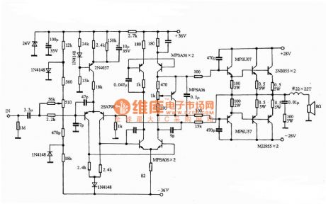
M22K Pioneer power amplifier circuit diagram
Published:2011/8/9 2:26:00 Author:Rebekka | Keyword: Pioneer, power amplifier
View full Circuit Diagram | Comments | Reading(7157)
Using temperature and frequency converter high-precision temperature control circuit diagram
Published:2011/8/9 2:28:00 Author:Rebekka | Keyword: high-precision temperature control

Because the RB changes with temperature, the fc also changes with temperature. Audio decoder phase lock loop uses a single audio decoder integrated circuit IC2 (LM567), the center frequency is xsl-fo = 1/1.1 Rw1C4. The adjustment of W1can setxsl-fotemperature frequency. When the IC1 oscillation frequency is the same with the center of the IC2, fc frequency xsl-fo is consistent. The LM567 outputs low level (8) foot) and makes relay J suck close. It will open the load. (View)
View full Circuit Diagram | Comments | Reading(1935)
Single-phase thyristor zero trigger electric stove temperature control circuit diagram
Published:2011/8/11 2:09:00 Author:Rebekka | Keyword: Single-phase thyristor, electric stove , zero trigger ,

The figure shows the single-phase thyristor zero trigger electric furnace temperature control circuit. This temperature device is composed of the signal detection temperature control circuit, the zero detection circuit, cycle switch, trigger control and digital display etc. Itis used withXCT-101 temperature control meter together. It can monitor the 6 ~ 8 kW single-phase thyristor zero trigger electric furnace temperature. The temperature and thermal insulation are ajustable in 1% ~ 99%. The winding I1 of transformer B1, D1 ~ D4, D6, C1, BG1 and other components form the zero pulse detection circuit, IC2-l (1 / 4 CD4011) is the controlling door, and in the effect of the pulse output by cycle switch (IC1), it outputs a group of zero-crossing detection pulse, which is inverting amplified by BG2 and output by isolated transformer BG3. (View)
View full Circuit Diagram | Comments | Reading(3137)
Front Mark Levisin JC-2 circuit diagram
Published:2011/8/11 2:03:00 Author:Rebekka | Keyword: Front Mark Levisin
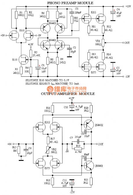
Front Mark Levisin JC-2 circuit diagram is shown as below.
(View)
View full Circuit Diagram | Comments | Reading(2446)
LM3886 BTL PA circuit diagram
Published:2011/8/11 2:03:00 Author:Rebekka | Keyword: BTL PA
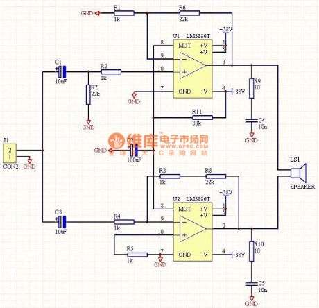
LM3886 BTL PA circuit diagram is shown as below.
(View)
View full Circuit Diagram | Comments | Reading(4295)
V.A.L VAA-70 push-pull tube amplifier circuit diagram
Published:2011/8/11 2:03:00 Author:Rebekka | Keyword: V.A.L , push-pull tube amplifier

V.A.L VAA-70 push-pull tube amplifier circuit diagram is shown as below.
(View)
View full Circuit Diagram | Comments | Reading(2915)
The piezo-electric transducer using high-impedance high-fidelity amplifier circuit diagram
Published:2011/8/11 2:12:00 Author:Rebekka | Keyword: piezo-electric transducer , high-impedance high-fidelity amplifier


The main parameters of the OPA604:
In the automatic control system or some detection system, the sensor piezoelectric devices is often used as sensor. So as to realize the power electrical signals. This kind of sensor equivalent sources has very high resistance and the signal is very weak. So it must also be matching high input impedance amplifier circuit, and the amplify circuit must also have the ability to accurately weaken signal amplifier. The figure gives high fidelity op-amp OPA604 constitute amplifier circuit.
(View)
View full Circuit Diagram | Comments | Reading(1371)
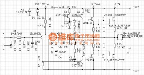
30W A-class OCL post amplifier circuit diagram
Published:2011/8/11 2:13:00 Author:Rebekka | Keyword: 30W A-class, OCL post amplifier
View full Circuit Diagram | Comments | Reading(1834)
The voltage follower circuit diagram
Published:2011/8/11 2:14:00 Author:Rebekka | Keyword: voltage follower

The figure shows the integration op-amp. When the input signal is too big, it may cause damage, even if integrated chip is not damaged, its work state have entered the nonlinear area. Figure (a) shows the circuit of the input signal to + l00V which is still working. The input voltage Vi increased to 3 pins. This circuit is the same phase, its input magnification is + 1, integrated chips is INA106, the chip is specially used for high voltage input follower. It normally uses withourt resistance. (View)
View full Circuit Diagram | Comments | Reading(892)
Eliminating ripple IOV fixed voltage power supply circuit diagram
Published:2011/8/9 2:06:00 Author:Rebekka | Keyword: Eliminating ripple, IOV fixed voltage , power supply

View full Circuit Diagram | Comments | Reading(781)
12V、5V Dual regulated power supply circuit diagram
Published:2011/8/4 21:43:00 Author:Rebekka | Keyword: 12V, 5V , Dual regulated power supply

View full Circuit Diagram | Comments | Reading(2845)
9V Tape Reader AC and DC Power Supply Circuit Diagram
Published:2011/8/9 2:05:00 Author:Rebekka | Keyword: 9V Tape Reader, AC and DC , Power Supply

View full Circuit Diagram | Comments | Reading(943)
5v Fixed power supply circuit diagram with short-circuit protection
Published:2011/8/9 2:22:00 Author:Rebekka | Keyword: short-circuit protection, fixed power supply

View full Circuit Diagram | Comments | Reading(1149)
5 V regulated power supply circuit diagram with doubler rectifier
Published:2011/8/9 2:21:00 Author:Rebekka | Keyword: 5 V , regulated power supply , doubler rectifier

View full Circuit Diagram | Comments | Reading(891)
4.5V Precision power circuit diagram
Published:2011/8/9 2:18:00 Author:Rebekka | Keyword: 4.5V Precision power

View full Circuit Diagram | Comments | Reading(840)
Simple constant temperature controllor circuit composed of 555
Published:2011/8/9 2:17:00 Author:Rebekka | Keyword: Simple , constant temperature controllor

Rt1 contacts the contact because of the heated expansion, but IC 6 feet is disconnected since the Rt2 is still at the low level, thus the trigger circuit skins. The temperature continue to rise to the upper limit value, Rt2 is conducted, the corresponding 6 feet potential is inhigh level (6 V), it is larger than 6 x two-thirds = 4 V trigger level. The IC resets, the (3) foot outputs low level, SCR stops and the electric heating wires power supply is disconnected. It stops heating. When the temperature drops, Rt2 will be disconnected. For 555 circuit is self-preservation and it still outputs low level feet by (3). When the temperature drops to the limit value, Rt1 is disconnected. (View)
View full Circuit Diagram | Comments | Reading(689)
Developer temperature control circuit diagram
Published:2011/8/9 2:13:00 Author:Rebekka | Keyword: Developer temperature control

The figure shows the developer temperature control circuit. When the power supply is open, the temperature is low, the value of the R1 is high, so that the 5G31 outputs high level because the input potential of the positive end is higer than the input potential of the negative end.The relay J suck closes, RL starts to heat because the power supply is open and makes the temperature high. When the temperature rise to the control temperature, the bridge turns to balance. The 5G31 outputs low level because the potential of negative input terminal is higher than the positive input terminal . The relay J is disconnected, RL stops to heat because the power supply is closed. (View)
View full Circuit Diagram | Comments | Reading(612)
Multichannel pressure gauge inspection circuit diagram
Published:2011/8/15 2:35:00 Author:Rebekka | Keyword: Multichannel pressure , gauge inspection

It uses more pieces of MAX1457 to match the monolithic A/D converter and single chip microcomputer to form the multi-channel pressure inspection instrument and the circuit diagram is shown as the chart. In the figure, it uses a piece of 8-1 analog switch CD4051 to receive 8-road sensor signals. The calibration coefficient of the each sensor is stored in 93C66. The output of the CD4051 connects with the ICL7135 4 1/2 bit monolithic A/D converter, then it uses the decoding driver (CD4511) and bit driver (MC1413) to drive 4 1/2 bit LED display. The 8051 single chip microcomputer decides one road sensor signal having completed A/d conversion by the DQS and BUSY signal output by ICL7135. (View)
View full Circuit Diagram | Comments | Reading(754)
Photoelectric isolated amplifier circuit composed of the ISO100
Published:2011/8/15 2:25:00 Author:Rebekka | Keyword: Photoelectric isolated amplifier
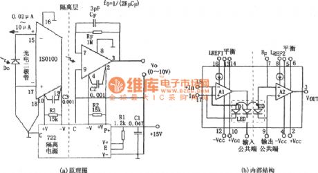
The figure shows the photoelectric isolated amplifier circuit. The photoelectric isolated amplifier can be used in the automatic control system, the data acquisition system, computer I/O interface and communications equipment. The photoelectric isolated amplifier is also called the photoelectric couplers, this device is a composite shell element that the light emitting components and the light components and packaging in the same relative set. The input and output contacts by light and ithas insulation to electric. It is the the solid component with completely an unique property and function. (View)
View full Circuit Diagram | Comments | Reading(640)
Bias compensation broadband amplification circuit diagram
Published:2011/8/11 2:11:00 Author:Rebekka | Keyword: Bias compensation, broadband amplification
The voltage amplifier multiples of the circuit parameters is: Av =-10, the voltage conversion speed is larger than 70 v/u s, half power bandwidth can be up to 400 kHz above, its gain products of bandwidth is about 30 MHz. The working temperature of the LH0003with10-pin metal circular encapsulates is 0 ~85 ℃. The storage temperature is 65 ~ 150 ℃. When it uses the LH0003 chip, its working temperature is 125 ℃ and 55, the storage temperature is 65 ~ 150 ℃. Figure (b) shows the LH0003 / LH0003C integrated chips tube feet arrangment diagram. (View)
View full Circuit Diagram | Comments | Reading(878)
| Pages:554/2234 At 20541542543544545546547548549550551552553554555556557558559560Under 20 |
Circuit Categories
power supply circuit
Amplifier Circuit
Basic Circuit
LED and Light Circuit
Sensor Circuit
Signal Processing
Electrical Equipment Circuit
Control Circuit
Remote Control Circuit
A/D-D/A Converter Circuit
Audio Circuit
Measuring and Test Circuit
Communication Circuit
Computer-Related Circuit
555 Circuit
Automotive Circuit
Repairing Circuit