
Circuit Diagram
Index 557
Bridge structure single amplifier circuit diagram
Published:2011/8/17 3:10:00 Author:Rebekka | Keyword: Bridge structure , single amplifier

View full Circuit Diagram | Comments | Reading(692)
Two functions four tones cycling burglar alarm circuit diagram
Published:2011/8/17 3:21:00 Author:Rebekka | Keyword: Two functions , four tones , cycling burglar alarm

View full Circuit Diagram | Comments | Reading(589)
Transistor 2SC5003, 2SC5250 internal circuit diagram
Published:2011/8/17 3:20:00 Author:Rebekka | Keyword: Transistor , internal circuit

Here is the schematic diagram of the transistor 2SC5003, 2SC5250 internal circuit diagram:
(View)
View full Circuit Diagram | Comments | Reading(1451)
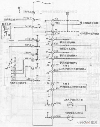
Accord sedan V6 engine electronic control system circuit diagram 3
Published:2011/8/16 3:11:00 Author:Rebekka | Keyword: Accord sedan , V6 engine , electronic control system
View full Circuit Diagram | Comments | Reading(542)
Beijing City Hunter BJ2O2OSG light off-road vehicle circuit diagram 2
Published:2011/8/16 3:19:00 Author:Rebekka | Keyword: Beijing City Hunter , light off-road vehicle
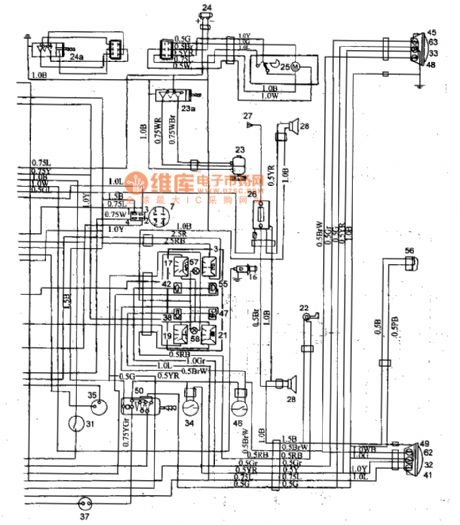
32,33 brake lights; 34 brake light switch; 35 turn the flash of a relay; 36 turn signal switch; 37 hazard warning flash relay; 38 left-turn signal; 39 former left-turn signal; 40 left turn signal; 41 rear left turn signal; 42 right-turn signal; 43 before the stone turn signal; 44 right turn signal; 45 after a turn signal; 46 reversing light switch; 47 reversing light; 48,49 reversing lamp; 50 light switch; 51 overtaking signal light switch; 52 opening of a change of light; 53,54 headlamp; 55 light beam; 56 license plate light; 57,58,59 instrument lights; 60,61 The width light; 62,63 taillight fuse box, the fuse in this order: speaker Fl, work light socket; F2 a turn signal, magnetic field, instrument; F3 heater, wiping, washing; F4 fog; F5 smoke detectors; F6 radio and tape player.Wire color code: R red; Y yellow; G green; L blue; V violet; Gr A gray; a brown; W white; B black; such as copper wire 0.5 BrW cross-sectional area is 0.5 m m, the basic color is brown (Br), and it has white stripes (W).
(View)
View full Circuit Diagram | Comments | Reading(966)
Beijing City Hunter BJ2O2OSG light off-road vehicle circuit diagram 1
Published:2011/8/16 3:19:00 Author:Rebekka | Keyword: Beijing City Hunter , light off-road vehicle
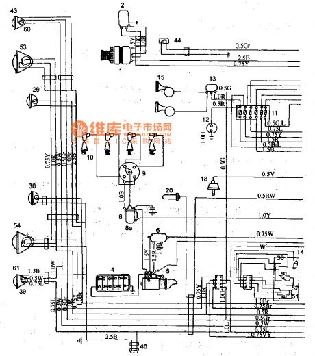
1 AC generator; 2 alternator regulator; 3 current meter; 4 battery; 5 starter; 6 starter relay; 7 little fire to open; 8-bit wide fire ignition coil coil tart additional resistance; 9 distributor; 10 spark plug; 11 fuse box (Fl-F6); 12 work light socket; 13 horn relay; 14 horn button; 15 speaker; 16 smoke detectors; 17 hydraulic table; 18 pressure gauge sensor; 19 thermometer; 20 thermometer sensor; 21 fuel gauge; 22 fuel gauge sensor; 23 heater motor; 23 defrost switch; 24 washing; 24 windshield wiper switch; 25, wiper motor; 26 Shoufang Ji; 27 day line; 28 speaker; 29,30 air fog lights; 31 for fog lamp switch. (View)
View full Circuit Diagram | Comments | Reading(782)
PSB8592 Microcomputer dial integrated circuit diagram
Published:2011/8/16 3:13:00 Author:Rebekka | Keyword: Microcomputer dial , integrated circuit

PSB8592 is microcomputer dial integrated circuit. It is applied to all communications for the use of dialing.
PSB8592 integrated circuit includes dial-up signal generation, coding and decoding key basins. It uses 20-pin dual in-line package, the pin functions and data of integrated circuit are listed in Table 1. (View)
View full Circuit Diagram | Comments | Reading(652)
Mitsubishi Pajero (PAJERO) light off-road vehicle taillight and headlight relay basic circuit diagram
Published:2011/8/16 3:10:00 Author:Rebekka | Keyword: Mitsubishi Pajero , light off-road vehicle, taillight and headlight relay

174 taillight relay; 175 headlamp relay; 176,177 headlamps; 178 light beam; 179 light switch; 180 overtaking signal dimmer switch and switch (View)
View full Circuit Diagram | Comments | Reading(1519)
Mitsubishi Pajero (PAJERO) brand light off-road vehicle seat belt circuit diagram
Published:2011/8/16 3:10:00 Author:Rebekka | Keyword: Mitsubishi Pajero , brand light off-road vehicle
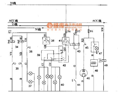
34 a seat belt electromagnetic valve; 35 a seat belt switch; 36 a brake light switch; 37 a brake light; 38 a turn signal flasher; 39 a turn signal switch; 40 a turn signal and turn signal; 41 a hazard warning flashers; 42 a hazard warning switch; 43 a horn; 44 a horn button; 45 rear heater switch; 46 rear heater motor; 47 except for a rear window defroster switch; 48 a rear window defroster; 49 a fuel cut solenoid valve Shan. (View)
View full Circuit Diagram | Comments | Reading(1235)
Mitsubishi Pajero light off-road vehicle automobile instrument wiring(with electroniccompass) circuit diagram
Published:2011/8/12 4:34:00 Author:Rebekka | Keyword: Mitsubishi Pajero, light off-road vehicle, automobile instrument wiring , electroniccompass
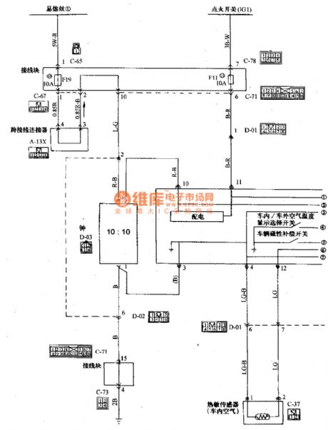
Mitsubishi Pajero light off-road vehicle meter(mounted electronic compass vehicle)wiring circuit diagram is shown as above.
(View)
View full Circuit Diagram | Comments | Reading(2253)
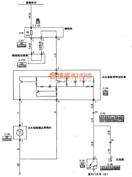
Mitsubishi Pajero light off-road vehicle ignition key core and floodlight wiring circuit diagram
Published:2011/8/12 4:32:00 Author:Rebekka | Keyword: Mitsubishi Pajero, light off-road vehicle , ignition key core , floodlight wiring
View full Circuit Diagram | Comments | Reading(2307)
The serial LED circuit driven by inductance booster transformer IC
Published:2011/8/11 21:38:00 Author:Borg | Keyword: serial LED, inductance booster transformer, IC


The serial white light LED circuit driven by inductance booster transformer is shown in the figure, by changing the values of R1 and VZ2 in the figure, the booster topology can drive more than one serial white light LEDs (HSMW-C850). By using the 47Ω ground resistor and 1.233V Vref, the component can provide with a 26mA current.
(View)
View full Circuit Diagram | Comments | Reading(1081)
The 24V regulated powers supply circuit with over-current protector
Published:2011/8/11 21:57:00 Author:Borg | Keyword: regulated powers supply, over-current protector

The 24V regulated powers supply circuit with over-current protector is shown as above.
(View)
View full Circuit Diagram | Comments | Reading(756)
A durable 0~20V regulated power supply circuit
Published:2011/8/11 21:59:00 Author:Borg | Keyword: regulated power supply

A durable 0~20V regulated power supply circuit is shown as above.
(View)
View full Circuit Diagram | Comments | Reading(1800)
A small-sized 15V and 1A parallel regulated power supply circuit
Published:2011/8/11 22:01:00 Author:Borg | Keyword: small-sized, parallel, regulated power supply

A small-sized 15V and 1A parallel regulated power supply circuit is shown as above.
(View)
View full Circuit Diagram | Comments | Reading(695)
Common 0~20v and 1A regulated power supply circuit
Published:2011/8/11 22:02:00 Author:Borg | Keyword: regulated power supply

The common 0~20v and 1A regulated power supply circuit is shown as above.
(View)
View full Circuit Diagram | Comments | Reading(977)
The application circuit of driving 5 white light LEDs
Published:2011/8/18 3:40:00 Author: | Keyword: application circuit, white light LEDs
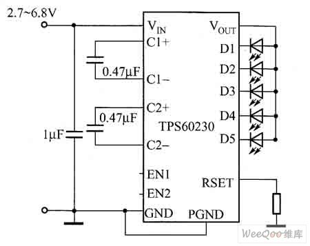
TPS60230 can drive 5 25mA white light LEDs at most; TPS60231 can drive 3 25mA white light LEDs at most; the main technology features of TPS60230/TPS60231 are shown as follows.①the brightness of the white light LED can be controlled by PWM; ②it has the 1 and 1.5 time shift modes of self-adaption, and it can get high efficiency; ③the shift frequency is 1MHz; ④the working input voltage range is 2.7~6.5V; ⑤it contains the soft starting circuit, by which the transient state influx current can be impeded; ⑥low input wave and low EMI(electromagnetic disturbance).
(View)
View full Circuit Diagram | Comments | Reading(967)
The white light LED driver circuit of high current
Published:2011/8/11 22:16:00 Author:Borg | Keyword: white light, LED driver, high current
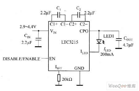

The white light LED driver circuit of high current can be formed by LTC3215, and its output current of the drive white light LED is 700mA. It can switch automatically among the voltage-multiplying types of 1, 1.5 and 2 times, which can make LTC3215 get a high efficiency of 92% in the whole working voltage range of the lithium ion battery. The typical application circuit of LTC3215 is shown in figure 1 and its efficiency curve is shown in figure 2.
Figure 1 The typical application circuit of LTC3215
Figure 2 the efficiency curve of LTC3215 (View)
View full Circuit Diagram | Comments | Reading(1104)
The separated element headphone amplifier circuit
Published:2011/8/11 22:18:00 Author:Borg | Keyword: separated element, headphone amplifier

The separated element headphone amplifier circuit is shown as above.
(View)
View full Circuit Diagram | Comments | Reading(843)
The self-halt hypnomelder circuit
Published:2011/8/17 22:43:00 Author: | Keyword: self-halt hypnomelder

The hypnomelder is full-functioned, and it can do many adjustments, the effect is also good. The square wave generator consists of BG1 and BG2, which can generate the hypnosis signal pulse. By adjusting resistor R2, the pulse width (i.e tune quality) can be controlled; by adjusting resistor R3, the pulse interval can be controlled. The best hypnosis signal can be got by repeated adjustment. By press switch AN, the circuit begins to work, it powers the pulse generator composed of BG1 and BG2, which makes the generator generate hypnosis signals.
(View)
View full Circuit Diagram | Comments | Reading(709)
| Pages:557/2234 At 20541542543544545546547548549550551552553554555556557558559560Under 20 |
Circuit Categories
power supply circuit
Amplifier Circuit
Basic Circuit
LED and Light Circuit
Sensor Circuit
Signal Processing
Electrical Equipment Circuit
Control Circuit
Remote Control Circuit
A/D-D/A Converter Circuit
Audio Circuit
Measuring and Test Circuit
Communication Circuit
Computer-Related Circuit
555 Circuit
Automotive Circuit
Repairing Circuit