
Circuit Diagram
Index 548
Bistable touching switch circuit
Published:2011/8/23 2:09:00 Author:Ecco | Keyword: Bistable touching switch

View full Circuit Diagram | Comments | Reading(813)
Emitter coupled bistable circuit
Published:2011/8/23 2:21:00 Author:Ecco | Keyword: Emitter coupled bistable

View full Circuit Diagram | Comments | Reading(664)
Emitter coupled monostable circuit
Published:2011/8/23 2:22:00 Author:Ecco | Keyword: Emitter coupled monostable

View full Circuit Diagram | Comments | Reading(699)
Emitter follower circuit
Published:2011/8/23 2:06:00 Author:Ecco | Keyword: Emitter follower

View full Circuit Diagram | Comments | Reading(1157)
Three steady-state circuit
Published:2011/8/23 2:05:00 Author:Ecco | Keyword: Three steady-state circuit

View full Circuit Diagram | Comments | Reading(599)
Tunnel diode bistable circuit
Published:2011/8/23 2:04:00 Author:Ecco | Keyword: Tunnel diode bistable

View full Circuit Diagram | Comments | Reading(1149)
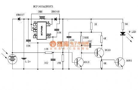
Solar night light
Published:2011/8/23 2:08:00 Author:Ecco | Keyword: Solar night light
View full Circuit Diagram | Comments | Reading(1715)
Tunnel diode astable circuit
Published:2011/8/23 2:04:00 Author:Ecco | Keyword: Tunnel diode astable

View full Circuit Diagram | Comments | Reading(990)
Tunnel diode monostable circuit
Published:2011/8/23 2:03:00 Author:Ecco | Keyword: Tunnel diode monostable

View full Circuit Diagram | Comments | Reading(1069)
Astable flashing circuit
Published:2011/8/23 2:07:00 Author:Ecco | Keyword: Astable flashing circuit

View full Circuit Diagram | Comments | Reading(642)
Stable single-button electronic switching circuit
Published:2011/8/23 2:24:00 Author:Ecco | Keyword: Stable single-button , electronic switching circuit

View full Circuit Diagram | Comments | Reading(637)
Mouse circuit diagram
Published:2011/8/23 2:02:00 Author:Ecco | Keyword: Mouse

View full Circuit Diagram | Comments | Reading(3839)
Manual contactor Y-△ buck starting circuit
Published:2011/8/23 1:59:00 Author:Ecco | Keyword: Manual contactor , Y-△ buck starting

View full Circuit Diagram | Comments | Reading(701)
Manually series reactance starting three-phase motor circuit
Published:2011/8/23 2:01:00 Author:Ecco | Keyword: Manually series, reactance starting , three-phase motor

View full Circuit Diagram | Comments | Reading(776)
LT1932 white LED driver circuit diagram
Published:2011/8/22 21:36:00 Author:Ecco | Keyword: white LED driver
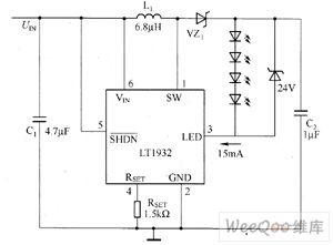
Linear Technology Corporation designs LT1932 boost DC / DC converter in order to provide the high-efficient constant drive current for white LED backlight. In order to obtain the best brightness matching, LT1932 uses drive white LED series way to protect all the series of white LED current to be matched and achieve the consistency of white LED brightness. The white LED backlight driver composed of LT1932 has conversion efficiency in generally 15% to 80%.
(View)
View full Circuit Diagram | Comments | Reading(1963)
MAX1576 White LED driver circuit diagram
Published:2011/8/12 2:06:00 Author:Lucas | Keyword: White LED driver
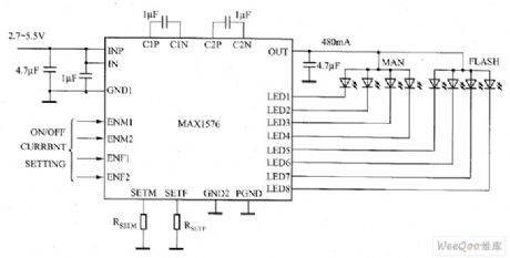
MAX1576 charge pump can drive eight white LEDs with a constant current regulation in order to achieve uniform light intensity. It can drive each group of (LED1 ~ LED4) white LED with 30mA current for backlighting. MAX1576 can achieve high efficiency in the whole operating voltage range of one lithium-ion battery. MAXl576 has lMHz fixed switching frequency, so it only uses few external components, and it also has low EMI and low input ripple. MAX1576 uses two external resistors to set the master flash white LED and white LED's largest (100%) current.
(View)
View full Circuit Diagram | Comments | Reading(832)
MAX1570 white LED driver circuit diagram
Published:2011/8/12 1:20:00 Author:Lucas | Keyword: white LED driver
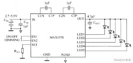
MAX1570 is 1 times voltage-multiplying mode, 1.5 times voltage-multiplying high-efficiency charge pump, which can drive up to five constant current white LEDs and get uniform brightness, and maintain the highest efficiency in the whole Li-Ion battery voltage range. MAX1570's fixed frequency is 1MHz, and it can select small external components. The optimized current regulation structure can ensure low EMI and low input ripple. It uses an external resistor to set full amount white LED current of MAX1570. Pulse-width modulation (PWM) signal can also be used to adjust the brightness of white LED.
(View)
View full Circuit Diagram | Comments | Reading(923)
MAX1573 white LED driver circuit diagram
Published:2011/8/12 3:09:00 Author:Lucas | Keyword: white LED driver
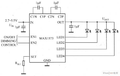
The main technical characteristics of MAX1573 charge pump are as follow: ① MAX1573 uses a tiny chip-scale (UCSP) package (4 × 4-bump, 2.1mm × 2.1mm × 0.6mm) and 16-pin thin QFN package (4mm × 4mm). ②it has proprietary adaptive 1x mode, 1.5x mode. ③ conversion efficiency (PLEDS / PBAT) is up to 92%. ④ the white LED current matching accuracy is 0.2%. ⑤ 28mA drive capability. ⑥ low input ripple and EMI. ⑦ without limiting resistor. ⑧ digital logic or PWM brightness control. ⑨ 0.1μA low shutdown current. ⑩ 2.7 ~ 5.5V input voltage range.
(View)
View full Circuit Diagram | Comments | Reading(958)
MAX8607 white LED driver circuit diagram
Published:2011/8/15 20:23:00 Author: | Keyword: white LED driver
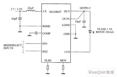
MAX8607 integrates a 1MHz PWM boost converter, 1.5A low dropout (LDO) current regulator, and logic control circuit, and it is suitable for small-size white LED flash design. MAX8607's two logic inputs control has four modes: ① shutdown modewith quiescent current decreasing to 0.1μA (typ). ② projection mode which provides 360mA continuous white light with LED current. ③ flash mode provides short 1.5A White LED current. ④ disk model provides +5 V external power supply (up to 1A) and the 80mA constant current for white LED driver.
(View)
View full Circuit Diagram | Comments | Reading(888)
MAX8595Z/MAX8596Z white LED driver circuit diagram
Published:2011/8/16 1:20:00 Author: | Keyword: white LED driver
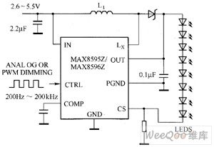
MAX8595Z/MAX8596Z's main technical characteristics are as follow. ① It uses 25mA current to drive eight white LEDs, and the temperature derating function allows less white LEDs to achieve the same brightness (MAX8596Z). ② it has 2.6 ~ 5.5V input voltage range, 12mVp-p low input ripple, and s direct PWM internal filter. ③ it has 86% efficiency (PLED / PIN). ④ it has flexible brightness control, 1.7% current regulation accuracy. ⑤ it has 1MHz PWM switching frequency, 0.1μF output capacitor. ⑥ it has soft-start, eliminate inrush current, and output overvoltage protection functions. ⑦ it has 0.3μA shutdown current.
(View)
View full Circuit Diagram | Comments | Reading(779)
| Pages:548/2234 At 20541542543544545546547548549550551552553554555556557558559560Under 20 |
Circuit Categories
power supply circuit
Amplifier Circuit
Basic Circuit
LED and Light Circuit
Sensor Circuit
Signal Processing
Electrical Equipment Circuit
Control Circuit
Remote Control Circuit
A/D-D/A Converter Circuit
Audio Circuit
Measuring and Test Circuit
Communication Circuit
Computer-Related Circuit
555 Circuit
Automotive Circuit
Repairing Circuit