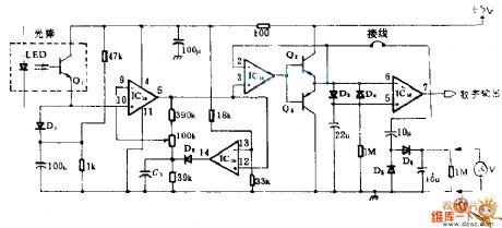
Amplifier Circuit
Optical wand amplifier circuit diagram
Published:2011/8/17 2:46:00 Author:Rebekka | Keyword: Optical wand amplifier | From:SeekIC

This circuit is mainly composed of light rods and four operational amplifier IC1, amplifier, and Lee silicon diode's exponential positive electrical properties can change the output of light rods into logarithmic e transformation voltage changes, its peak - peak is proportional to the white, black light currents ratio, and it has nothing to do with the absolute value. IC1b, which is the comparator, and peak detection D2-C1 clamp the output of amplifier IC1 to a fixed potential. Thus, the signal after amplification and clamping is transformed into binary digital microprocessor output. Output is compatible with TTL.
Reprinted Url Of This Article:
http://www.seekic.com/circuit_diagram/Amplifier_Circuit/Optical_wand_amplifier_circuit_diagram.html
Print this Page | Comments | Reading(3)

Article Categories
power supply circuit
Amplifier Circuit
Basic Circuit
LED and Light Circuit
Sensor Circuit
Signal Processing
Electrical Equipment Circuit
Control Circuit
Remote Control Circuit
A/D-D/A Converter Circuit
Audio Circuit
Measuring and Test Circuit
Communication Circuit
Computer-Related Circuit
555 Circuit
Automotive Circuit
Repairing Circuit
Code: