Other Circuit
ICBT Grid Electrode Driving Control Power Circuit
Published:2011/8/16 10:35:00 Author: | Keyword: ICBT, Grid Electrode, Driving, Control, Power | From:SeekIC

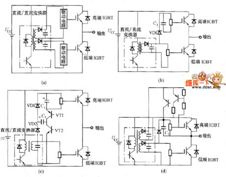
The ICBT grid driving circuit itself is using the hybrid method. Its internal optocoupler type, high-voltage type IC would make it small. But the control power, which provide power for the grid electrode driving circuit, should use the transformer and smoothing capacitor and so on. For the driving circuit overall miniaturization, it should consider the miniaturization of these elements. So it would take different ways for the control circuit, which are shown in the picture. The picture (a) is transformer method. It is a stable power of which the high and low side IGBT can get the same voltage. The picture (b) is the bootstrap method. The C1 is the bootstrap capacitance. The VD1 should select the high-voltage diode. The inverter's output duty cycle shouldn't be 100%.
Reprinted Url Of This Article:
http://www.seekic.com/circuit_diagram/Electrical_Equipment_Circuit/Other_circuit/ICBT_Grid_Electrode_Driving_Control_Power_Circuit.html
Print this Page | Comments | Reading(3)

Article Categories
power supply circuit
Amplifier Circuit
Basic Circuit
LED and Light Circuit
Sensor Circuit
Signal Processing
Electrical Equipment Circuit
Control Circuit
Remote Control Circuit
A/D-D/A Converter Circuit
Audio Circuit
Measuring and Test Circuit
Communication Circuit
Computer-Related Circuit
555 Circuit
Automotive Circuit
Repairing Circuit
Code: