Remote Control Circuit
Water Quality Detector Circuit
Published:2011/7/20 3:18:00 Author:Joyce | Keyword: Water Quality , Detector | From:SeekIC

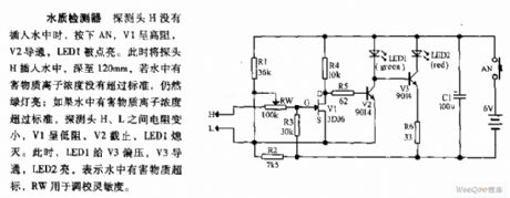
The water quality circuit is as shown in the figure:
Water Quality Detector Circuit: When the detecting head has not been inserted into the water, if one presses AN, V1 will display that the impedance is high, V2 will break over and LED1 will be lightened. Once inserting the detecting head into 120mm deep under the water, the green light will still be on if the concentration of ions of harmful substance has not exceeded the standard. If not so, the impedance between detecting head H and L will become smaller. Then V1 will show low impedance, V2 will cut off, and LED1 will go out. At this time, LED1 will offer bias voltage to V3 which will break over afterwards. And LED2 will be lightened, indicating harmful substance in the water has exceeded the standard. RW is used to adjust the sensitivity.
Reprinted Url Of This Article:
http://www.seekic.com/circuit_diagram/Remote_Control_Circuit/Water_Quality_Detector_Circuit.html
Print this Page | Comments | Reading(3)

Article Categories
power supply circuit
Amplifier Circuit
Basic Circuit
LED and Light Circuit
Sensor Circuit
Signal Processing
Electrical Equipment Circuit
Control Circuit
Remote Control Circuit
A/D-D/A Converter Circuit
Audio Circuit
Measuring and Test Circuit
Communication Circuit
Computer-Related Circuit
555 Circuit
Automotive Circuit
Repairing Circuit
Code: