Remote Control Circuit
Cooking Timer Circuit
Published:2011/7/20 3:17:00 Author:Joyce | Keyword: Cooking , Timer | From:SeekIC

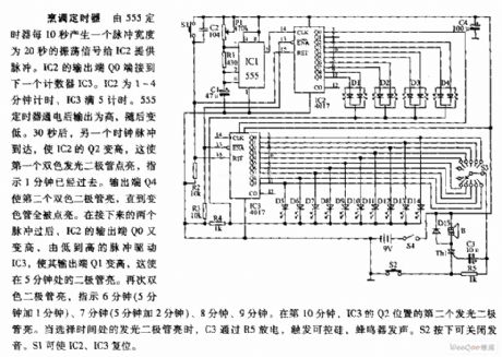
Cooking timer circuit is as shown in the figure:
Cooking Timer: Oscillating signal of 20 seconds pulsing width is produced by timer 555 every 10 seconds to provide pulse for IC2. The output end Q0 of IC2 is connected with the next timer IC3. The timing time of IC2 is 1~4 minutes and that of IC3 is 5 minutes. After the timer 555 is provided with power, its output is high, but becomes low afterwards. 30 seconds later, the arrival of another clock pulse will increase the value of Q2 of IC2, which indicates that 1 minute is gone by. The output end Q4 will lighten the first two-tone diode till the whole color tube is lightened. After the next two pulses, output end Q0 of IC2 becomes high again. The pulse changing from low to high will drive IC3 and increase its output end Q1. This will lighten the diode which is set at the point of 5 minutes.
Reprinted Url Of This Article:
http://www.seekic.com/circuit_diagram/Remote_Control_Circuit/Cooking_Timer_Circuit.html
Print this Page | Comments | Reading(3)

Article Categories
power supply circuit
Amplifier Circuit
Basic Circuit
LED and Light Circuit
Sensor Circuit
Signal Processing
Electrical Equipment Circuit
Control Circuit
Remote Control Circuit
A/D-D/A Converter Circuit
Audio Circuit
Measuring and Test Circuit
Communication Circuit
Computer-Related Circuit
555 Circuit
Automotive Circuit
Repairing Circuit
Code: