Other Circuit
Comparator Circuit of TL431
Published:2011/8/3 7:04:00 Author:Michel | Keyword: Comparator Circuit | From:SeekIC

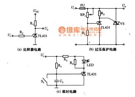
The picture a,b,c are comparator circuits of TL431.The picture (a) is comparator circuit of TL431.When input voltag9be Ui≥2.5V,the output voltage U。=2V;Ui<2.5V,the output U。=Ucc.
The picture (b) is protection voltage of TL431.When input voltage Ui exceeds 1+RRP1/R1)UREF, a larger current flows through the fuse,FU burns out to achieve the purpose of voltage protection.The picture (c) is delay circuit of TL431,the voltage on C1 is zero,TL431 stops and LED does not shine.With C1 charging voltage rises,TL431 conducts, LED displays by shining.The delay time(from input voltage to LED shining)is R1C1ln[Ui/(Ui-UREF)].S1 is reset switch, when it is connected,C1 discharges and prepares for the next delay.
Reprinted Url Of This Article:
http://www.seekic.com/circuit_diagram/Amplifier_Circuit/Other_circuit/Comparator_Circuit_of_TL431.html
Print this Page | Comments | Reading(3)

Article Categories
power supply circuit
Amplifier Circuit
Basic Circuit
LED and Light Circuit
Sensor Circuit
Signal Processing
Electrical Equipment Circuit
Control Circuit
Remote Control Circuit
A/D-D/A Converter Circuit
Audio Circuit
Measuring and Test Circuit
Communication Circuit
Computer-Related Circuit
555 Circuit
Automotive Circuit
Repairing Circuit
Code: