Other Circuit
Infrared Control Telephone Code Lock Circuit
Published:2011/8/1 0:31:00 Author:Michel | Keyword: Infrared Control, Telephone Code Lock | From:SeekIC

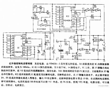
The infrared control telephone code lock emitting circuit is composed of VD4026-3 and peripheral components. R1 resistance value decides the IC internal oscillator oscillation frequency, here it's 100 KHz.IC 14 feet is control circuit.14 feet outputs low PWL and 17 feet outputs address serial pulse and launches infared adjusting pulse when S is pressed.Receiving circuit:VD1 receiving signal is amplifiedvia F1 and it's surged and then it outputs serial pulse via F3.IC2 is decoding circuit of transmitter IC.When the decoding is finished successfully,high PWL is output from 17 feet,the positive pulse makes F4 and F5 monostable circuit enter transition state and it outputs 10s positive pulsr and the pulse make relay K actuate 10 S.
Reprinted Url Of This Article:
http://www.seekic.com/circuit_diagram/Amplifier_Circuit/Other_circuit/Infrared_Control_Telephone_Code_Lock__Circuit.html
Print this Page | Comments | Reading(3)

Article Categories
power supply circuit
Amplifier Circuit
Basic Circuit
LED and Light Circuit
Sensor Circuit
Signal Processing
Electrical Equipment Circuit
Control Circuit
Remote Control Circuit
A/D-D/A Converter Circuit
Audio Circuit
Measuring and Test Circuit
Communication Circuit
Computer-Related Circuit
555 Circuit
Automotive Circuit
Repairing Circuit
Code: