
Circuit Diagram
Index 1395
VEHICLE_AUDIO_AMPLIFIER_INVERTER
Published:2009/6/19 4:53:00 Author:May
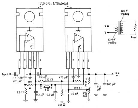
An audio amplifier can drive a step-up transformer to obtain 120 Vac. (View)
View full Circuit Diagram | Comments | Reading(743)
SIMPLE_INVERTER
Published:2009/6/19 4:52:00 Author:May

View full Circuit Diagram | Comments | Reading(712)
ELECTRONICALLY_CONTROLLED_VARIABLE_GAIN_VIDEO_LOOP_THROUGH_AMPLIFIER__
Published:2009/6/19 4:51:00 Author:May
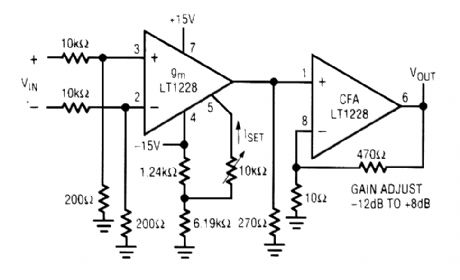
An LT1228 transconductance amplifier iS used in this application The gain is adjustable from-12to+8dB. (View)
View full Circuit Diagram | Comments | Reading(542)
VIDEO_FADER
Published:2009/6/19 4:50:00 Author:May

Using two LT1228 transconductance amplifiers in front of a current feedback amplifier forms a video fader. The ratio of the set currents into pin 5 determines the ratio of the inputs at the output. (View)
View full Circuit Diagram | Comments | Reading(2)
Infrared remote control dimmer, speed controller diagram 1
Published:2011/6/26 20:36:00 Author:Nora | Keyword: Infrared, dimmer, controller

AC 220V voltage filtered by R2-limiting step, VDl rectifier, VS regulator and Cl, C2. It provide DC voltage about 5V for ICl-IC3 (Vcc).In pressing the remote control button, the remote control infrared remote control pulse(the time is less than 0.45 when press the remote control button , the remote control application output pulses 1-3; if the remote control button press time over .45 , the output of the remote control more than 3 Burst). 1C1 will receive the infrared pulse train amplification, demodulation, and plastic surgery and other treatment, output a low pulse, the VD2 turn, C3 quickly discharges. When the voltage across C3 is lower than Vcc / 3 时, IC2's output of 3 feet high, so that V conduction. When through a pulse train, VD2 end, +5 V voltage charging of C3 by the RP, the IC2 pin 2, 6-pin voltage rise, when the voltage is increased to 2Vcc / 3 时, lC2 flip-circuit, 3-pin change low, V cut-off. If the new moon in the C3 charge between ICl and output a low pulse, C3 will discharge again, then keep the output of IC2 3 feet high. (View)
View full Circuit Diagram | Comments | Reading(2422)
1_kW_10_kHz_SINE_WAVE_INVERTER
Published:2009/6/19 4:49:00 Author:May

SCRs can produce considerable power at frequencies up to 30 kHz or more. This circuit can supply 1 kW at 10 kHz. The load is shown as an equivalent load, and practically this will be the primary of the transformer for isolation purposes. The power supply can be a 120-V bridge rectifier and filter combination. (View)
View full Circuit Diagram | Comments | Reading(746)
POSITIVE_TO_NEGATIVE_dc_dc_INVERTER
Published:2009/6/19 4:48:00 Author:May
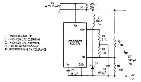
If a source of negative 5 Vdc is needed and only a positive supply is available, this circuit can be used. (View)
View full Circuit Diagram | Comments | Reading(769)
SCR_INVERTER_AND_TRIGGER_CIRCUIT
Published:2009/6/19 4:47:00 Author:May

In this circuit, L1 and C5 are used as commutating elements. L1 resonates quency corresponding to the half period of the waveform. (View)
View full Circuit Diagram | Comments | Reading(895)
Thermostat, governor diagram 2
Published:2011/6/26 21:02:00 Author:Nora | Keyword: Thermostat, governor , diagram

When the power selector adjust the switch S, it can change the capacitor charge and discharge rate of Cl, thus change the thyristor conduction angle. Cl through V to the voltage across the trigger and make it turn-VT, by changing the conduction angle of VT to change the electric heater EH (load) both ends of the AC voltage level. VLl and VL2 for the working status indicator LEDs. Placed in the S l stalls, VL2 light; the S placed in the 4 stalls, VLl light. (View)
View full Circuit Diagram | Comments | Reading(909)
DIFFERENTIAL_VIDEO_LOOP_THROUGH_AMPLIFIER
Published:2009/6/19 4:47:00 Author:May
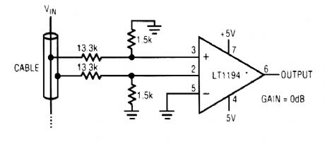
An LT1194 is used as a differential amplifier for video applications, where low cable loading is needed. (View)
View full Circuit Diagram | Comments | Reading(637)
TWO_INPUT_VIDEO_MULTIPLEX_CABLE_DRIVER
Published:2009/6/19 4:45:00 Author:May

CMOS logic levels select one of two video in-puts with this circuit. The op amps are Linear Technology LT1190s (View)
View full Circuit Diagram | Comments | Reading(715)
TCL 8988 mobile phone maintenance circuit diagram
Published:2011/5/6 1:49:00 Author:Jessie | Keyword: mobile phone maintenance
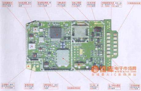
View full Circuit Diagram | Comments | Reading(610)
MULTIPLE_INPUT_VIDEO_MULTIPLEX_CABLE_DRIVER
Published:2009/6/19 4:44:00 Author:May


Using a Linear Technology LT1227, the mul-tiplex video amp uses logic levels to tum on and off selected inputs. (View)
View full Circuit Diagram | Comments | Reading(673)
INTERFACING_RESISTIVE_TRANSDUCERS
Published:2009/6/19 4:44:00 Author:May
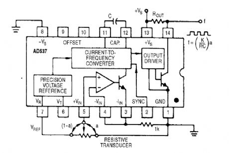
All types of resistive-element transducers, such as servo-pots, level indicators, thermistors, photosensors, strain gages, and so on, can be directly connected to the AD537. The scale-correction factor, K, is a function of resistance, varying from 0.65 to 0.98 for values from 3 to 100 kΩ. (View)
View full Circuit Diagram | Comments | Reading(1170)
TIMER_ac_LINE_INTERFACE
Published:2009/6/19 4:43:00 Author:May

This circuit illustrates the use of an optoisolator to enable the control of a triac connected to the ac line and load, while maintaining dc and ac isolation between the ac line and the timer circuit. A 555 or other timer circuit can be used. (View)
View full Circuit Diagram | Comments | Reading(3081)
KEY_ILLUMINATOR
Published:2009/6/19 4:42:00 Author:May

Used as a 10-second momentary illuminator, this circuit can be useful in other applications as well. Pressing S1 charges C1, which holds Q1 on and holds the LED lit for about 10 seconds. (View)
View full Circuit Diagram | Comments | Reading(733)
ac_INTEGRATOR
Published:2009/6/19 4:41:00 Author:May

This op-antp circuit can be used with a wide variety of op amps. The values of Rf and Ri depend on gain, but will be 1 kΩ to 1 MΩ in most cases. Cf depends on the pole frequency needed. U1 is a 741-type op amp, etc. (View)
View full Circuit Diagram | Comments | Reading(1577)
SOIL_HEATER_FOR_PLANTS
Published:2009/6/19 4:41:00 Author:May

A TDA1024 electronic thermostat senses soil temperature via thermistor R6. The circuit uses zero-crossing switching of the heater. The heater is made of elastic-coated steel wire. P1 is used to set the temperature. The heater should have 2 Ω or more resistance and operate from the 9-V transformer. About 40W of heat is available. (View)
View full Circuit Diagram | Comments | Reading(3636)
SIMPLE_INTEGRATOR
Published:2009/6/19 4:40:00 Author:May

View full Circuit Diagram | Comments | Reading(605)
INTEGRATOR_WITH_BIAS_CURRENT_COMPENSATION
Published:2009/6/19 4:39:00 Author:May

View full Circuit Diagram | Comments | Reading(2)
| Pages:1395/2234 At 2013811382138313841385138613871388138913901391139213931394139513961397139813991400Under 20 |
Circuit Categories
power supply circuit
Amplifier Circuit
Basic Circuit
LED and Light Circuit
Sensor Circuit
Signal Processing
Electrical Equipment Circuit
Control Circuit
Remote Control Circuit
A/D-D/A Converter Circuit
Audio Circuit
Measuring and Test Circuit
Communication Circuit
Computer-Related Circuit
555 Circuit
Automotive Circuit
Repairing Circuit