
Circuit Diagram
Index 1384
The damming switch power supply circuit
Published:2011/7/21 3:42:00 Author:Seven | Keyword: damming switch, power supply circuit


The circuit adopts with a TOP202Y integrated circuit. The damming control loop consists of VTl, VT2, Rl~R4 and IC2. VT1 and VT2 have the consistent parameters, which compose the mirror image current source. The output features of the damming switch power supply is shown in the figure, the output curve can be divided into 3 areas: the constant voltage area, the damming area and the auto restart area. In the figure is the damming switch power supply circuit and curve. (View)
View full Circuit Diagram | Comments | Reading(613)
INPUT_GUARDING_FOR_HI_ZOP_AMPS
Published:2009/6/22 23:27:00 Author:May

View full Circuit Diagram | Comments | Reading(569)
TACHOMETER_DERIVED_FROM_BRUSHLESS_SHAFT_ANGLE_RESOLVER
Published:2009/6/22 23:26:00 Author:May

The tachometer circuit operates in conjunction with a brushless shaft-angle resolver. By performing a sequence of straight-forward mathematical operations on the resolver signals and utilizing a simple trigonometric identity, it generates a voltage pro-portional to the rate of rotation of the shaft.The figure illustrates an analog tachometer circuit that processes the input and output signals of a two-phase, brushless, transformer-type shaft-angle resolver into a signal with instantaneous amplitude proportional to the instantaneous rate of rota-tion of the shaft. The processing in this circuit effects a straightforward combination of mathematical operations leading to a fi-nal operation based on the well-known trigonometric identity [sin(x)]2 + [cos(x)]2 = 1 for any value ofx.The resolver is excited with a periodic waveform; a sinusoid is indicated in the figure, but a square, triangular, or other peri-odic waveform could be used instead. Thus, the two outputs of the resolver are k1 sin(ωt)sin(θ) and k1 sin(ωt)cos(θ), where k1 is a constant proportional to the amplitude of excitation, cot is 2nm the frequency of excitation, t is time, andθis the instantaneous shaft angle.The two outputs of the resolver are then processed, along with a replica of the sinusoidal excitation, by demodulators. These signals are then differentiated with respect to time in two differentiator circuits. Notice that dB/dt is the rate of change of the shaft angle and is the quantity that one seeks to measure.Next, a multiplier circuit forms a product of the demodulator and differentiator outputs proportional to sin(θ), and the prod-uct of the demodulator and differentiator outputs proportional to cos(θ), The output of the cosine multiplier is fed to a unit-gain inverting amplifier. (View)
View full Circuit Diagram | Comments | Reading(1699)
The miniature electron accounts price scale composed of S8 low price electron weigh chip
Published:2011/7/21 3:07:00 Author:Ecco | Keyword: miniature electron accounts price scale , electron weigh chip

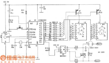
The S8, S9 are two kinds of electron weigh chip in low price, the common characteristics of two model can be summarized as they can directly drive liquid crystal display(LCD), and they can account price and weigh. It's suitable to constitute small scaled or miniature electronic scale. The telephone that is constituted a miniature electron to account price scale by the S8 is shown as chart. Only using 3 slabs of integrated circuits in the telephone:IC1(S8), IC2(four lucks put LM324), IC3(the 2 Kb E2 PROM chip LC56), the electron accounts all of the price scales to adopt a table put up component and measures the accuracy as 1%~0.5%, the volume is small, the cost is low, it's suitable quantity production.
Its main function is as follows: To account price and heavy, to accumulate times, to accumulate figure , display clock, the intelligence to cut of and select rangeabilities of 10 kg, 15 kg, 50 kg and 80 kg, to set null adjustment and null tracking, auto peeling, clear function, a prompt to error, overload indication, low -voltage indication. (View)
View full Circuit Diagram | Comments | Reading(567)
BASIC_OP_AMP_AUDIO_AMPLIFIER
Published:2009/6/22 23:26:00 Author:May

Any general-purpose op amp can be used in this application. (View)
View full Circuit Diagram | Comments | Reading(3865)
The manufacturing circuit of infrared reception controller
Published:2011/7/21 3:34:00 Author:Seven | Keyword: manufacturing circuit, infrared reception controller
View full Circuit Diagram | Comments | Reading(456)
COMPUTALARM
Published:2009/6/22 23:25:00 Author:May

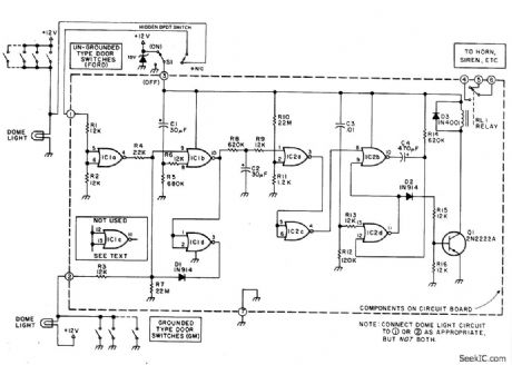
The circuit has a built-in, self-arming feature. The driver turns off the ignition, presses the arm button on the Computalarm, and leaves the car. Within 20 seconds, the alarm arms itself-all automatically! The circuit will then detect the opening of any monitored door, the trunk lid, or the hood on the car. Once acti-vated, the circuit remains dormant for 10 sec-onds. When the 10-second time delay has run out, the circuit will close the car's horn relay and sound the ham in periodic blasts (approxi-mately 1 to 2 seconds apart) for a period of one minute. Then the Computalarm automatically shuts itself off (to save your battery) and re-arms. If a door, the trunk lid, or the hood re-mains ajar, the alarm circuit retriggers and another period of horn blasts occurs. The Com-putalarm has a key switch by which the driver can disarm the alarm circuit within a 10-second period after he enters the door. The key switch consists of a closed circuit jack, J1, and a mating miniature plug. (View)
View full Circuit Diagram | Comments | Reading(0)
ATMOSPHERE_NOISE_MONITOR
Published:2009/6/22 23:21:00 Author:May

Tune an unmodified transistor radio to an unused frequency near 540 kHz that's free of broad-cast-station interference; the receiver is used to pick up sferics. The received signal is fed from the receiver's earphone jack through a patch cord to the input jack(J1)of the circuit. The back-to-back audio transformers, T1 and T2, provide a suitable impedance match and signal level when the unit is used with various receivers.Diode Dl rectifies the audio input from the receiver to pulsating dc, which is filtered by C1, R1, and C2 to provide a time constant of several minutes. That dampens out fluctuations in most cases, unless lightning flashes are very infrequent.The voltage appearing at the output of the filter is a function of signal strength transferred by C1.Switch 51 is included to prgvide a convenient way to discharge the capacitors, if adjustments are re-quired during a monitoring session.Integrated circuit U1(one section of an LM324 quad pro op amp)is used as a high input-resis-tance voltmeter. Resistors R2 and R3 determine amplifier gain, and potentiometer R4 is used to ad-just full-scale meter deflection for a suitable voltage level at the input. A value of 1.5 V has been satisfactory for use with several receivers tried, but they can be changed.If the monitor is to be used only as a meter, the milliammeter can be connected directly between R4 and chassis ground, omitting R5, 53, J2, and J3. The latter components provide suitable output for use with a chart recorder having a full-scale range of either 10 mV or 1 mA. The circuit, when powered from a 9-V battery, draws about 1 mA. (View)
View full Circuit Diagram | Comments | Reading(0)
HUM_REDUCER_FOR_DIRECT_CONVERSION_RECEIVERS
Published:2009/6/22 23:20:00 Author:May
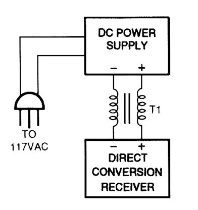


One cure for ac power line hum and ripple (caused by leakage current) is to use a well-regulated and filtered 9- to 18-Vdc power supply with a balancing choke (T1 in this illustration) between the power supply and the DCR. (View)
View full Circuit Diagram | Comments | Reading(0)
PRACTICAL_DIFFERENTIATOR
Published:2009/6/22 23:18:00 Author:May

A differentiator has a high-pass charactenstic. Components are chosen by using the design equations. (View)
View full Circuit Diagram | Comments | Reading(0)
QUAD_TONE_OSCILLATOR
Published:2009/6/22 23:40:00 Author:Jessie

A quad op amp (TL084, etc.) can be used to produce four audio tone generators for use in a test setup. The circuit uses a 12-V supply. (View)
View full Circuit Diagram | Comments | Reading(2886)
CAPACITANCE_MULTIPLIER
Published:2009/6/22 23:17:00 Author:May

View full Circuit Diagram | Comments | Reading(0)
ELECTRONIF_THERMOSTAT
Published:2009/6/22 23:16:00 Author:May
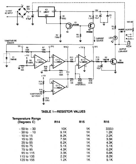
A diode, such as a IN4148, has a typical -2m V/℃ temperature coefficient at a 1 mA diode cur-rent. Q1 and Q2 form a constant current source. D1 is the temperature sensor. IC1-a and -b are dc amplifiers, with IC1-c a temperature reference voltage supply. IC1-d is a comparator with variable hysteresis. R14, R15, and R16 are chosen depending on the thermostat range desired. Q3 is a relay driver (2N3904). The relay used should handle the Ioad current or an optoisolator triac combination can be used. (View)
View full Circuit Diagram | Comments | Reading(0)
TELEVISION_VERTICAL_DEFLECTION_CIRCUIT
Published:2009/6/22 23:40:00 Author:Jessie

Two transistors are used to drive the yoke(2.5 mH + 0.3Ω) in this deflection circuit. R8 samples the yoke current and provides feedback to Q2, resulting in a very linear current ramp through the yoke. (View)
View full Circuit Diagram | Comments | Reading(1425)
PHASE_LOCKED_LOOP
Published:2009/6/22 23:15:00 Author:May

The PLL will lock onto an input signal. Both triangle- and square-wave outputs are available.A quad op amp can be used in this circuit, which should be useful in the audio and LF radio region. (View)
View full Circuit Diagram | Comments | Reading(0)
The differential light detecion circuit
Published:2011/7/21 2:55:00 Author:Seven | Keyword: light detecion circuit

figure 2-120 The differential light detecion circuit (View)
View full Circuit Diagram | Comments | Reading(532)
EASILY_TUNED_SINE_WAVE_OSCILLATOR
Published:2009/6/22 23:39:00 Author:Jessie

The circuit will provide both a sine-and square-wave output for frequencies from below 20 Hz to above 20 kHz. The frequency of oscillation is easily tuned by varying a single resistor. This is a considerable advantage over Wien bridge circuits, where two elements must be tuned simultaneously to change frequency. Also, the output amplitude is relatively stable when the frequency is changed.An operational amplifier is used as a tuned circuit, driven by square wave from a voltage comparator. Frequency is controlled by R1, R2, C1, C2, and R3, with R3 used for tuning. Tuning the filter does not affect its gain or bandwidth, so the output amplitude does not change with frequency. A comparator is fed with the sine-wave output to obtain a square wave. The square wave is then fed back to the input of the tuned circuit to cause oscillation. Zener diode, D1, stabilizes the amplitude of the square wave fed back to the filter input. Starting is ensured by R6 and C5, which provide dc negative feedback around the comparator. This keeps the comparator in the active region (View)
View full Circuit Diagram | Comments | Reading(1810)
LOW_TEMPERATURE_SENSOR
Published:2009/6/22 23:13:00 Author:May

A negative bias current can produce the off-set needed for below-zero readings using the LM34 or LM35 temperature sensor. (View)
View full Circuit Diagram | Comments | Reading(0)
The laser diode drive circuit
Published:2011/7/21 2:59:00 Author:Seven | Keyword: laser diode, drive circuit

Figure 2-146. The laser diode drive circuit (View)
View full Circuit Diagram | Comments | Reading(693)
VEHICLE_SECURITY_SYSTEM
Published:2009/6/22 23:39:00 Author:Jessie
This alarm gives a 15-20 second exit and entrance delay. After being triggered, the alarm sounds for five minutes and then shuts off. Once triggered, the sequence is automatic and is not affected by subsequent opening or closing of doors. (View)
View full Circuit Diagram | Comments | Reading(1018)
| Pages:1384/2234 At 2013811382138313841385138613871388138913901391139213931394139513961397139813991400Under 20 |
Circuit Categories
power supply circuit
Amplifier Circuit
Basic Circuit
LED and Light Circuit
Sensor Circuit
Signal Processing
Electrical Equipment Circuit
Control Circuit
Remote Control Circuit
A/D-D/A Converter Circuit
Audio Circuit
Measuring and Test Circuit
Communication Circuit
Computer-Related Circuit
555 Circuit
Automotive Circuit
Repairing Circuit