
Circuit Diagram
Index 1380
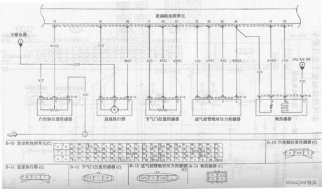
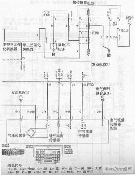
KIA Maxima Car Engine Circuit (the 2nd)
Published:2011/7/17 23:56:00 Author:Felicity | Keyword: KIA Maxima, Car Engine Circuit, (the 2nd)
View full Circuit Diagram | Comments | Reading(704)
Audio oscillator with adjustable frequency composed of μA741
Published:2011/7/28 2:22:00 Author:Ecco | Keyword: Audio oscillator , adjustable frequency
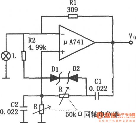
The chart shows the audio oscillator circuit with adjustable frequency. The circuit uses the lamp control circuit gain, but also increases the automatic gain control circuit composed of zener diode D1, D2 and resistor R2. As the frequency dropping, the output amplitude will increase. When the output amplitude increases to a predetermined value, zener diode is conducted, therefore, the amplifier gain reduces, so that it can avoid amplifier saturation. R2 is used to reduce the limiting effect of zener diode to avoid excessive distortion. Increasing R2, D1, D2 can make the adjusting range of oscillation frequency change from the 3:1 to 10:1. Using the components in figure, the oscillation frequency range is 200Hz ~ 2kHz. If R1, C1, C2 select the components with low temperature coefficient, then the temperature changes in the range of -55 ℃ ~ +125 ℃ , frequency stability is ± l%.
(View)
View full Circuit Diagram | Comments | Reading(660)
KIA Maxima Car Engine Circuit (the 1st)
Published:2011/7/17 23:54:00 Author:Felicity | Keyword: KIA Maxima, Car Engine Circuit, (the 1st)

View full Circuit Diagram | Comments | Reading(685)
SINE_WAVE_CONVERTER
Published:2009/6/22 23:54:00 Author:May

This circuit produces a sine wave with a low-frequency clock input. The clock rate should be 100Hz or less. (View)
View full Circuit Diagram | Comments | Reading(0)
DITHERIZER
Published:2009/6/22 23:54:00 Author:May

In digital audio, a noise signal of amplitude less than one significant bit is often added to the au-dio to reduce the quantizing effect and improve the audio quality by trading digital noise for ana-log noise, which does not have the harsh sound. This circuit consists of a noise generator to add a low level of noise to an analog signal to be digitized, or an analog signal from a digital source. (View)
View full Circuit Diagram | Comments | Reading(0)
DRIVEN_FLYBACK_CONVERTER
Published:2009/6/22 23:53:00 Author:May

This circuit uses an SG1524 Silicon General regulating pulse width modulator and provides ±15 V from a 5-V supply rail. (View)
View full Circuit Diagram | Comments | Reading(0)
PULSED_TONE_ALARM,GATED_BY_A_HIGH_INPUT,WITH_DIRECT_DRIVE_OUTPUT
Published:2009/6/22 23:53:00 Author:May

View full Circuit Diagram | Comments | Reading(0)
12_BIT_DAC
Published:2009/6/22 23:52:00 Author:May

This circuit uses an Analog Devices DAC-8043 12-bit multiplying DAC The output will be D/4096×Vref where D is the numerical value of the digital input word(0 to 4095) Vref is 1.235 volts in this cicuit (View)
View full Circuit Diagram | Comments | Reading(0)
ELECTRONIC_KEYER
Published:2009/6/23 1:40:00 Author:Jessie

This circuit automatically produces Morse code dots and dashes set by time constants involving C1 and C2. R1 sets dot/dash ratio and R2 sets the speed. R5 sets the relay drop-out point. (View)
View full Circuit Diagram | Comments | Reading(997)
REPEATER_BEEPER
Published:2009/6/23 1:38:00 Author:Jessie

The signal from COR triggers U1 which produces a beep-gate pulse that enables the analog gate consisting of D2 and D3 to pass the beep tone generated by U2. (View)
View full Circuit Diagram | Comments | Reading(880)
CURRENT_TO_VOLTAGE_CONVERTER_WITH_BOOST_TRANSISTOR
Published:2009/6/23 1:38:00 Author:Jessie
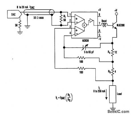
A transistor such as the MJE200 can be added to an Analog Devices AD830 to produce this current to voltage converter. Loads to 250 mA can be driven. The 5- to 65-pF trimmer is for compensation. (View)
View full Circuit Diagram | Comments | Reading(780)
SIMPLE_INTERCOM_FOR_NOISY_ENVIRONMENTS
Published:2009/6/22 23:51:00 Author:May
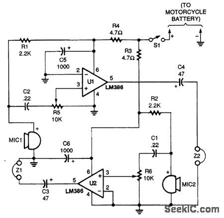
This intercom was originally designed for motorcycle to passenger communications A simple"passenger-to-pilot”ttercom circuit is shown. Two LM386 ICs are connected in a low-gam amplifiercircuit with the headphone output of one paired to the microphone input of the other The microphones are electret elements and the earphones can be of the in-ear type or of the small stereo/monotype that with fit inside a helmet Both amplifiers in the circuit operate at a minimum gain of 20 dB. (View)
View full Circuit Diagram | Comments | Reading(0)
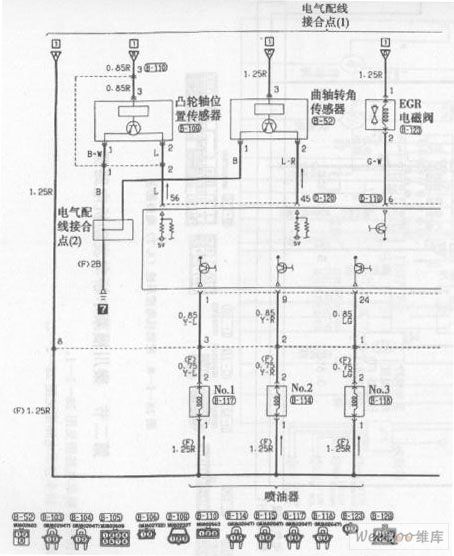
Beijing Pajero SUV Engine Control System (M / T) Circuit (the 5th)
Published:2011/7/18 0:10:00 Author:Felicity | Keyword: Beijing Pajero SUV Engine Control System (M / T) Circuit (the 5th)
View full Circuit Diagram | Comments | Reading(737)
AUTO_BURGLAR_ALARM_1
Published:2009/6/22 23:50:00 Author:May

View full Circuit Diagram | Comments | Reading(0)
180~224kHz Carrier frequency generator
Published:2011/7/28 3:21:00 Author:Ecco | Keyword: 180~224kHz , Carrier frequency , generator
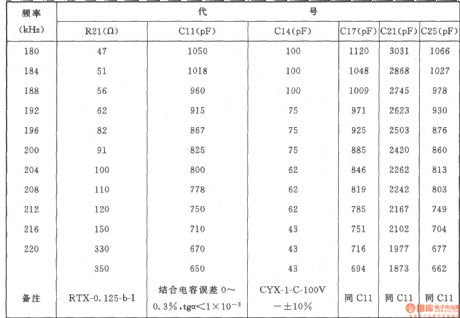
The generator shown in the chartcan be used in the channel modulation of carrier, the channel carrier frequency has 12 kinds:180kHz、184kHz、188kHz、192kHz、 196kHz、200kHz、204kHz、208kHz、212kHz、216kHz、220kHz、224kHz.
Component selection: Resistors: Rl、R48:3.9k、R2、R3、R8、R25、R32、R47:10k,R4、R9、R49、R52:3.3k,R5、R36:2k,R6、Rl9、R33、R41:20k,R7:24k,Rl0:110Ω,Rll:4.7k,Rl2:750Ω,Rl3、R23、R31、R50:1.3k,R14:560Ω,Rl5、Rl7、Rl8、R37、R38:510k,Rl6:910Ω,R20:16Ω,R21(See the table below),R22、R30:lk,R24、R29:300Ω,R26、R34、R43:2.7k,R27:180Ω,R28:1.5k,R35:240Ω,R39:300k,R40:1M,R42、R46:9.1k,R44:4.3k,R45:5.1k,R51:100k. The model is RTX-0.125W.
Potentiometer RPl: 4.7k,RP2:150Ω,RP3:680Ω,RP4:2.2kΩ.
Capacitor Cl C3,C7, Cl5, Cl6、C26~C29:0.047pF,C2, Cl9, C30:0.1μF,C4:510pF, C5, C8, C9, C20, C21~C24:5μF30V,C6:2400pF, Cl0(optical using when measurement ), Cll, Cl4, Cl7, C21, C25, see the table below, Cl2:20pF, Cl3:680pF, Cl7:5500pF, Cl8, C31, C32:50μF30V, C33, C34:0.22μF.
Diode: VD1, VD2, VD5, VD7~VDll, VDl4, VDl5:2CKl8 or 2CK72C, VDl2, VDl3, VDl7, VD20:2CPl4.
Regulator VD3, VDl6: 2CW5 (Current is6mA, regulator voltage is 12.5 ± 0.5V), VD4: 2CWl4 (voltage is 6.8 ± 0.2V), VDl9: 2DW7C. Varactor VD6i 2CC5.
LED VDl8: BT-201. Transistor VTl, VT4 ~ VT6, VT8 ~ VTl0: 3DG6C, β = 85 ~ 115, VT2: 3AG43, β = 50 ~ 85, VT3: 3DK28, β = 65 ~ 115, VT6, VTll: 3DGl28, β = 65 ~ 115 .
Relay K:] RW-3M. Inductance L: LH2A-straight-220μH (Inductors). Pulse transformer Tl: Model MX0-200, Ll-3, wound 12 turns, L2-3, L4-5, L6-7, L8-9are around with 24 turns, they are made of high strength magnet wire with Φ0.21mm.
(View)
View full Circuit Diagram | Comments | Reading(954)
Beijing Pajero SUV Engine Control System (A / T) Circuit (the 1st)
Published:2011/7/18 0:13:00 Author:Felicity | Keyword: Beijing Pajero SUV, Engine Control System (A / T), Circuit, (the 1st)
View full Circuit Diagram | Comments | Reading(715)
TTL_BASED_AUDIO_OSCILLATOR
Published:2009/6/22 23:49:00 Author:May

Half a 7404 will produce a tone around 1000 Hz with this circuit. (View)
View full Circuit Diagram | Comments | Reading(0)
AUDIO_VOLUME_LIMITER
Published:2009/6/22 23:49:00 Author:May

In this circuit,amplifier IC1-a provides signal amplification of 40 to+40 dB depending on thevalue of the LDR The LDR(ight dependent resistor)is driven by rectified audio from voltage follower IC1b and bridge rectifier D1 through D4 (View)
View full Circuit Diagram | Comments | Reading(0)
SSB signal generated by phase shift
Published:2011/7/28 3:26:00 Author:Ecco | Keyword: SSB signal , phase shift

Home SSB transmitter is a challenge to the HAM and a test to its own power. But up to now little HAM can self-make SSB transmitter, the main reason is the core components of the transmitter SSB-crystal filter and the matching crystal (such as crystal filters are equipped with 9MHz the 8998.5kHz, 9001.5kHz crystal) is difficult to purchase in the country, in this case, the phase shift method can generate SSB signals, comparing with the commonly used filter, but it has the advantages of easy make, low-cost, particularly the output frequency of VFO (should have a very high degree of frequency stability) can be directly taken as the firing frequency, it does not have to go through one or more frequency, greatly simplifying the whole circuit , the circuit is shown as the chart.
(View)
View full Circuit Diagram | Comments | Reading(1929)
BLOWN_FUSE_ALARM
Published:2009/6/22 23:49:00 Author:May
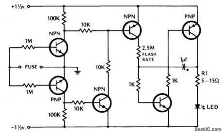
If the fuse blows, the LED indicator starts to blink. (View)
View full Circuit Diagram | Comments | Reading(0)
| Pages:1380/2234 At 2013611362136313641365136613671368136913701371137213731374137513761377137813791380Under 20 |
Circuit Categories
power supply circuit
Amplifier Circuit
Basic Circuit
LED and Light Circuit
Sensor Circuit
Signal Processing
Electrical Equipment Circuit
Control Circuit
Remote Control Circuit
A/D-D/A Converter Circuit
Audio Circuit
Measuring and Test Circuit
Communication Circuit
Computer-Related Circuit
555 Circuit
Automotive Circuit
Repairing Circuit